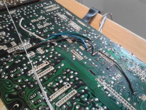
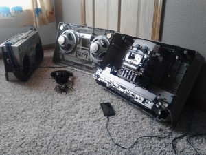
Fixing a legend.....

Superduper

Moderator
Staff member
Straight jumper. For example, if you look at the schematic and it shows a leg of resistor "R1" going to the collector leg of transistor "Q1" and the schem shows nothing in between, and you can confirm as much that only the traces on the pcb bridges those two points, then it should be "zero" ohms. 18 ohms on the other trace is just incidental to the design of the PCB and something deemed to be within acceptable tolerance and not something that would have a major affect on the circuit. In other words, not critical. In your case, because you have a problem common to both channels, the fix should affect both channels equally. If on the other hand, you have an issue that only affects one channel, the fix could affect balance between the two sides if not performed equally. For example, if one side had resistance of 8k ohms on the affected area and the parallel equivalent on the other side was zero ohms then there could be an audible or operational disparity. However, let me just say that once on a Hitachi TRK-8080, a similar broken trace issue manifest that took forever to find and involved "printed" resistors. The circuit diagram I had was for a different suffix version and did not match to the board I was working on. One printed resistor was completely open and I just took a guess and tacked a 10k (just going by memory only) ohm discrete resistor in it's place thinking I would tailor the resistor value based on the results observed. It restored the channel and I observed no audible difference between the two sides. Perhaps I guessed right on the proper resistance but I doubt it. More likely the value was not critical in this application. On other circuits, however, such as if the resistance is used to set transistor bias current or RC circuits which are calibrated, etc, then it would be far more critical to have the proper value reinstalled.

Anyhow, simple answer -- just a straight jumper and don't look back. It "might" even fix your problem.
 

blu_fuz

Well-Known Member
Staff member
I love when I get goose bumps when I read great info like that.


I'm a bit excited to look at it again and confirm or not that this is something I can jump.


These darn kids are really holding me up! :lol:


Thanks for the explination/example Norm.
 

Superduper

Moderator
Staff member
Geez Freddie, if there ever was a case of getting slung onto a wide tangent......... er that may just be it, haha.
 

blu_fuz

Well-Known Member
Staff member
Alright, I confirmed 10+ times on 3 different days that the spot we talked about needs to be jumped.

I jumped it!


I was focusing my next tests around the really corroded acid leaked part of the board that was pictured earlier that is now cleaned up.......

My results aren't good :-(. I'm finding atleast another 3-4 bad printed traces in that area. What's strange is one of the traces goes from vias, to vias, to vias, without crossing through the board to feed any real trace, then the last vias it crosses through the board to a real trace.

I'm confused why they would breakup the line so much with vias' if they weren't needed?
 

blu_fuz

Well-Known Member
Staff member
I've got the bad traces jumped. Yippie!

That battery acid f'd them up bad yikes.


I have one more trace in question. Continuity is there but I have a reading of 30 ohm of resistance from pad to pad. Jump it or leave it?
 

blu_fuz

Well-Known Member
Staff member
Decided to stick it back together for a quick test.


Nothing is better. It still has the same hum.


Other test results:
- line out hooked to M70, same hum in the audio signal through the M70's speakers
- headphones plugged into 5353, same hum in headphones
- MP3 player hooked into 5350 line in, same hum and faintly hear the MP3 playing as before
 

Superduper

Moderator
Staff member
There might be more bad traces or bad solder joints. You need to do more homework to confirm.

Via's act like little hollow tunnels that connect traces from top side of board to bottom side of board. Not sure what you mean when you say you have vias that don't connect to anything underneath. Is there a hole underneath at all? Also, are you sure there are no printed resistors within those top traces? If there were, then you'll need to refer to the circuit diagram and find out what the original values were.

If you are getting the hum out of the line-out jacks, then the issue is not in the amplifier, or even the tone board. It will be in a part of the circuit fore of those, which suggests preamp. There might be some IC's in the preamp area. A preamp chip where both channels flow through would be more suspect than any area of the circuit that is limited to only one channel.

At this point, the easiest way to proceed (although because of how the board mounts within the 5350, it's not easy at all), is to trace with an audio signal tracer. It is an instrument that is basically a high impedance, high gain amplifier with a probe. The probe is used to probe at various locations of the audio signal path and the results can be heard through the instrument. Due to varioius signal strengths along the way, the internal amplifier gain of the instrument will need to be constantly adjusted to hear but basically, the procedure is to start at the beginning of the audio path (line-in, using an audio source or audio signal injector). Then work your way forward using the circuit diagram and board diagram as a guide. When you find a point where the problem manifests, that's where you should focus on. For example, if you probe the input of an audio coupling capacitor and the sound is good, then probe the other end of the same capacitor and the issue manifests, then you've found the source of your problem.

There is another way is to use a audio signal injector. Basically using this method, you will probe from the opposite direction starting at the speakers and work your way back to the line-in jacks. The internal boombox amp and speakers will act as your listening device and the principle is the same as with the signal tracer above.

Sorry if this is starting to get a little involved and technical than you had planned but this is the world of electronics and it's not a discipline that can be learned in a few days or even weeks.
 

Superduper

Moderator
Staff member
Joe, the service manual should have a block diagram. It's not a "true" circuit diagram but rather a simplistic visual guide to the signal flow. Think of it as a simplified flow chart. It will give you an idea where you might want to look. Remember that your issue is common to both channels (it is, isn't it?). So don't focus on areas that are channel independant. That actually narrows it down quite a bit.
 

blu_fuz

Well-Known Member
Staff member
Thanks Norm for getting me on another possible path. Yes, the motorboating is even in both channels for line out, headphones, and speakers and can be faded to eather L/R with same sound.


I'm learning a lot even though this project has gotten way more involved than I ever thought it would.


Ill start by checking over printed traces again and then work on the audio path.

;)
 

blu_fuz

Well-Known Member
Staff member
I'm finding that signal tracers are a thing of the past!


Would this work for testing my setup or do you have a recomendation:


http://www.elexp.com/kit_2114.htm


Looks like radshack has a neat little option for signal tracing:

http://www.radioshack.com/product/index.jsp?productId=2062620


And this thing is interesting:

http://vk2rh.com/test-gea/qrpkits-signal-tracer-injector/


I have these same speakers to make my own!!! Help me make this:
https://www.youtube.com/watch?v=7CyclsFc31U

Looks like I found the original video:
http://video.ketnooi.com/video/CxRRlAYZfvI/dc-portable-signal-tracer-af-and-rf.html
https://www.youtube.com/watch?v=CxRRlAYZfvI
 

Superduper

Moderator
Staff member
You may say audio signal tracers are a thing of the past but really only because electronics have changed so much over the years that they aren't really applicable much in todays electronics. It certainly is not the only tool. You can inject a known waveform and trace with an oscilloscope too. But to be honest a signal tracer is far more useful and quicker in diagnosing issues with audio amplifers unless you are schooled in and know how to read (and even how to set up) an oscilloscope to produce a waveform, then you need to interpret the results. With the tracer, you can hear in an instant without having to take your eyes off the probe while with an oscilloscope, you'll need to view. Also, you can very easily hear the "quality" of the audio whereas with the scope, you can only "hear" with your eyes. Do you know what you are seeing or can you picture in your head what the picture in your eyes will sound like in your ears? Bottom line.... you are fixing a 35 year old device. Absolutely nothing wrong with using an instrument widely used 20-30 years ago.

As for the examples you showed... the handheld probe kit does sound interesting, but I don't see an attenuator. You will be testing everything from low line levels, to amplifier output levels. How will you attenuate the signal? As for using the home speaker to make your own.... I think you are far better off purchasing a commercial product designed for that purpose. You won't save that much making your own, and you also know nothing about the input impedance rating, don't have the probes or the jacks and such which will need to be purchased. By the time you are done, how much have you saved compared with using a product specially designed for signal tracing that was tested and has specs? It's important to know that high impedance is an absolute MUST. That is because when you probe a circuit, you need to know that your probe did not introduce a load onto the circuit causing it to not operate right. In other words, if you probe a circuit and you hear nothing, is it because the circuit shut down due to the additional loading introduced by the probe, or is it because the circuit is bad? Also, commercial products usually come with specially designed probes. I use a heathkit one that includes a high impedance vacuum tube amplifier with a built in vacuum tube cats eye that gives you a visual as well as selectable audio output. It has attenuators and the probe is switchable for RF or Audio signals. On one of the videos, the guy said you can hear a hum due to the flourescent lamps. Well, as you use that device, and you hear a hum, how will you intepret that? Is the hum part of the audio from your boombox, or is it from a nearby transformer or overhead lamps? I do not recall my heathkit ever picking up stray signals like that. In fact, the probe uses a shield cable with a signal ground. The home made ones uses regular unshieled probe wires that acts like antennas picking up anything and everything. You want to selectively test deliberate circuits, not accumulate random signals. Finally, none of those that I've seen (except maybe the probe kit... maybe) includes a coupling capacitor in the probe. This is important to block out DC. Otherwise, if you accidentally probe a 90v rail (certainly possible in a home stereo receiver), what happens to your home-made computer speaker tracer? Will it blow up?

In the end, you can experiment by building your own, but since specially designed instruments for that purpose don't cost much, and used vintage ones are very reasonably priced, I suggest you stick with a commercial instrument rather than a home built one with unknown specs and parameters. An unknown instrument testing an unkown working condition piece of gear results in unknown results.

I currently use this model:
[ebay]271389050893[/ebay] I'm not suggesting you buy this one, just telling you which model I personally use. There's another one right now on eBay at a current bid of $1.29 + shipping. There are more others even, some made by heathkit, some by Eico, etc. Before I spend one dime building my own custom computer speaker tracer, I would exhaust these options first. I might even buy/build that $35 pen probe one. I like the idea of an op amp based tracer because op amps have very low signal loading characteristics. However, that one requires ear buds. Hmmmm, if you accidentally probe a high level signal when you expected a low level signal and you have earbuds in your ear, does it blow out your ear drums? I know many times, I've probed a location to have the tracer emit a loud blast so with ear buds on........... Just wondering. Just saying.....

Oh and one last thing. Say you purchased one of those signal tracers for $30, or $35, or $99. When you are done and feel you don't need it anymore, I'll bet you can get close to what you paid for it. In other words, costed you close to nothing except the cost of shipping which you can chalk off as rent, provided you didn't get more. If you got a great deal or if you wish to take a hit, heck, I might buy it from you. But say you spend $10 or $20, or $35 to buy all the connectors, probes, jacks, switches, pots, etc etc to retrofit your own hack computer speaker signal tracer... what do you think the chances are someone will buy that from you? What do you think the chances of someone wanting to pay shipping for that thing, even offered for free? :hmmm:
 

blu_fuz

Well-Known Member
Staff member
Oh yah I see what you mean.


I searched epay and saw the vintage machines. I read one description and it mentioned needing work and something about tubes, so I figured why buy another 'thing' I will need to fix to use properly when I already have my 5350 as a project.......

Then I was looking for new stuff or DIY since the broken vintage stuff looked over priced.


Ill try to track down something local on craigslist while I watch that other auction you mentioned.


Thanks.
 

Superduper

Moderator
Staff member
Don't buy a known broken one, and make sure they are complete with probes or you will pull your hair out trying to find them. Because they are vintage, you might need to be patient to find a good one but I've looked and they do come up from time to time. If the seller says it's tested and working, I would definitely pay more for that one than an unknown incomplete one. The hassles of getting a non-working one or trying to find parts to complete an incomplete one is for the birds. In the end, it will cost you the same/more than just getting a good one in the first place, sans the hassles. It's not unusual for the seller to say they know nothing about it, especially if it belonged to their dad or dead uncle. But if they tell you for sure it's bad, or you can see damage to the probes, pass and don't look back. IF you can find a modern signal tracer, and it looks decent quality, then you can go for that too. I would definitely go for an opamp one over a transistorized powered one though due to the very low loading characteristics. Don't worry too much about the vacuum tube ones. They are vacuum tube for a reason, they perform well in these applications. Look closely at those vintage instruments and the front panels. You will see that the modern ones are nothing but a probe and speaker (or audio jack). Without adjustments, I don't see how it can be as valuable of a tool. I say this once again because you will be tracing from low level signals, to preamped and finally all the way up to the output level (speaker level). That ranges from inaudible to speaker blowing levels. I don't know enough about the idiot proof ones but unless there is a calibrated attenuator that tells you the level of the input signal gain level to achieve a certain amount of sound, how will you know if the signal being picked up is at the right amplitude for where it is in the circuit you are testing?