Fixing a legend.....
- Thread starter blu_fuz
- Start date
You are using an out of date browser. It may not display this or other websites correctly.
You should upgrade or use an alternative browser.
You should upgrade or use an alternative browser.
BoomboxLover48
Boomus Fidelis
Kenpat said:Don't rush yourself, Joe. This kind of work takes time.
Step by step.
 100%
100%  100%
100% 
baddboybill
Boomus Fidelis
I had the M90 deck with the burnt trace issue and it's very hard to try and repair especially since they are so close to each other and with my eye sight and unsteady hands I just had to give up. It's a shame there are not more 5350's out there to get parts from 
Bad Boy Bill

Bad Boy Bill
I might be lucky with the 5350 because the traces aren't as close together as the M90 ones are. I'm hoping that after some cleaning of the board I will see obvious damaged areas that can be bypassed from pad-to-pad with a wire jumper or even if I have to peel sections o traces off the board and lay new pieces, I'm OK with that too.
Thanks for the support guys. This thing looks too nice not to try and bring it back to life.
Thanks for the support guys. This thing looks too nice not to try and bring it back to life.
BoomboxLover48
Boomus Fidelis
Fixing traces with jumpers is fun! I've done the worst PCB crack with almost 12 lines broken.
Data cable and phone wires are the best for this work.
I used a razor blade to scratch and expose the line breaks from the crack, find a jumper spot/point with minimum components not to heat up during the soldering. Use heatsink not to heat up components. Always check continuity to make sure you are connecting the right places.
I would check the bottom and top of the board in good light to look for any PCB cracks also.
Even in the mid fifties I still got very steady hands and good eyesight.

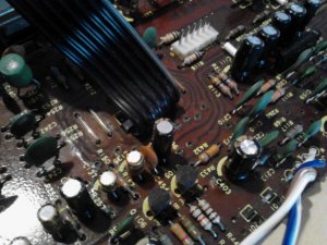
You guys are misunderstanding, these traces are not copper foil like on the bottom side, they are literally printed (imagine "painted" on with conductive paint) and resistors are "printed" using carbon paint? See R117, R168 and R268; those are actual printed resistors. If they are bad, you'll have to cut the trace with an exacto knife and "patch" in a discrete resistor using the nearest copper pad. Once again, you can't solder to the printed traces. Also the "vias" which are the holes that bridge the upper and lower traces can go bad too. And when you bridge using jumpers, that can introduce another set of issues if you take another route or if the new route strays too far from the board especially on low signal circuits since the boards are usually designed and tested with the traces in orig location. New route can result in new noise or interference as the jumpers act like mini antennas.
BoomboxLover48
Boomus Fidelis
Please see a line crack I had to fix on my RX5350. I used a jumper from appropriate places. No you cannot connect to traces. You need to find the right solder points for jumpers.
This made my left VU meters go dead. I had to spend a lot of time to figure out. I traced the problem to this crack and fixed it.
These kind of hair line cracks are so hard to see. I used a signal tracer and found this.
On panny diagram the blue lines show the signal path. They have PCB lines on top and bottom of the board from what I remember.
Attachments
BoomboxLover48
Boomus Fidelis
You will be fine Joe!blu_fuz said:I picked a real gem to try and fix!
Sooner or later you will find the problem! It is never easy working on old electronics. I've spend months fixing issues.
Today I spend 6 hours replacing belts on my mini Panny. It was a real challenge even though I had everything cleaned up and ready except for the belts to come in the mail from studio electronics.
Now it looks like I have to use small small belts instead of small belts. I might have to go through the whole process one more time.
BoomboxLover48
Boomus Fidelis
Looks very clean!blu_fuz said:
Thanks! It really needed it, thanks for the tips.
Ok a couple questions:
1. I have watched youtube vids on testing the removed capacitors, but still can't seem to figure out if that 4700uf 25v cap was/is good or not. What setting do I need to put my meter on?
2. When doing continuity tests, when I probe across a resistor is my miltimeter supposed to beep? It doesn't at some resistors. I can test long sections of circuits but some resistors kill the continuity test.....
I have a digital radioshack multimeter and for some reason the english instructions are missing so I'm trying to translate the spanish so I can use it lol.
Beosystem10
Member (SA)
Trouble is that testing caps out of circuit with the capacitance range on a meter isn't going to give you the whole story, you'd do well to test for ESR, equivalent series resistance. I found a link that explains this much more succinctly than I would:
Click this.
Knowing the capacitance value of a cap is mainly of use if they're all good and you need to find the right one to use when maybe their markings are worn away. Inexpensive DMMs tend not to do capacitance in any case so my apologies if you were already looking at other parameters.
You should also read this.

BoomboxLover48
Boomus Fidelis
Very good links!Beosystem10 said:Trouble is that testing caps out of circuit with the capacitance range on a meter isn't going to give you the whole story, you'd do well to test for ESR, equivalent series resistance. I found a link that explains this much more succinctly than I would:
Click this.
Knowing the capacitance value of a cap is mainly of use if they're all good and you need to find the right one to use when maybe their markings are worn away. Inexpensive DMMs tend not to do capacitance in any case so my apologies if you were already looking at other parameters.
You should also read this.

 John the Great!
BoomboxLover48
Boomus Fidelis
Joe, I know you are a very qualified person.
Sorry for presenting some basic stuff that might help you! There always something new to learn in our lives...and it never ends.
I like this guy!
https://www.youtube.com/watch?v=InJhgwmj2So
https://www.youtube.com/watch?v=Kqa51Femytw
http://www.ladyada.net/library/metertut/continuity.html
http://www.ladyada.net/library/metertut/resistance.html
To test a capacitor, you can use the capacitance setting of your DMM. However, most such DMM's only test for capacitance and does not measure ESR. You can also check using the ohms setting. It should not be shorted. Most likely, it will start counting up towards infinity, and the rate depends upon the capacitance. However, like I said, that 4700uf cap is merely a ripple filter anyhow and in my view, it's not even worth testing since it's doubtful related to your issue. You've already ordered it so just install it and be done with it. No point doing a recap and leaving an old one in.
When testing resistors, you should not be using the tone feature of the DMM, which is more intended for a continuity test. Resistors have........... resistance, which depending upon it's value, will result in the meter emitting a tone, or not. Depends upon the resistance threshold of your particular meter.
Speaking of continuity testing... you are testing traces, not continuity THROUGH resistors unless you also add the expected values of the inline resistors and include those into your readings. Also, if you can find a ground rail, you will notice while studying the schematic that many capacitors will terminate at ground. In general, you can expect the (-) lead to terminate at ground. You can clip one end of your dmm lead to a ground rail and probe all the caps that should terminate at ground. If a cap is supposed to terminate at ground but results in high resistance (or open), then you have a problem and need to investigate further.


 .
.

