Fixing a legend.....

blu_fuz

Well-Known Member
Staff member
I did replace that 4700uf cap, I was just trying to test the old one for shits and giggles to get familiar with using my DMM.


I was testing traces as far as I could follow them without getting lost. I checked continuity with the beep on the meter. I'm sure I could be testing more but it is esy to get tangled up trying to follow traces while flipping the board. Either way, I didn't find anything yet that throws a red flag.
 

-GZ-

Member (SA)
Superduper said:
To test a capacitor, you can use the capacitance setting of your DMM. However, most such DMM's only test for capacitance and does not measure ESR. You can also check using the ohms setting. It should not be shorted. Most likely, it will start counting up towards infinity, and the rate depends upon the capacitance. However, like I said, that 4700uf cap is merely a ripple filter anyhow and in my view, it's not even worth testing since it's doubtful related to your issue. You've already ordered it so just install it and be done with it. No point doing a recap and leaving an old one in.

When testing resistors, you should not be using the tone feature of the DMM, which is more intended for a continuity test. Resistors have........... resistance, which depending upon it's value, will result in the meter emitting a tone, or not. Depends upon the resistance threshold of your particular meter.

Speaking of continuity testing... you are testing traces, not continuity THROUGH resistors unless you also add the expected values of the inline resistors and include those into your readings. Also, if you can find a ground rail, you will notice while studying the schematic that many capacitors will terminate at ground. In general, you can expect the (-) lead to terminate at ground. You can clip one end of your dmm lead to a ground rail and probe all the caps that should terminate at ground. If a cap is supposed to terminate at ground but results in high resistance (or open), then you have a problem and need to investigate further.
Yeah...that's exactly what I was gonna say. ;)
 

blu_fuz

Well-Known Member
Staff member
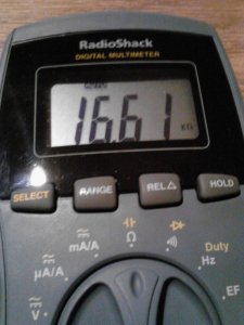
Okey dokey. I was doing some resistance tests (I hope) and most of the readings from one end of a trace to the other end were coming back with nice low resistance numbers (all under 1.0). Now I just probed this trace from one pad to the next pad and I got a resitance reading of over 16! Is this a high reading? Possible problem spot?


0126141917.jpg
 

Superduper

Moderator
Staff member
Hope you know your meter is returning 16k ohms and not 16. If you know that's a straight trace and no resistor inline, that's a problem. Confirm that there's nothing between those two points on the schematic. The pad itself may not show on the scheme but the component tethered to or near that pad should be.
 

blu_fuz

Well-Known Member
Staff member
I understand it showing me ohms, because I don't understand 100% what that 16 meant I posted the picture of the meter reading so I didn't miss anything in my description.


Shoot, now looking at it again I see I didn't follow the trace properly and it squiggled around, so that reading wasn't from pad to pad. Sorry about that.


Ill double check the other reading I had at 15+ to see if I followed it properly too.
 

Superduper

Moderator
Staff member
Ok, but pay close attention to the meter readings because like I said, 16 and 16k ohm is way different. You said 16 but your meter was showing 16,000 ohms. You may also see 16 with a small "m" which really means 16 megohms (16,000,000 ohms).
 

Superduper

Moderator
Staff member
Your meter is an autoranger, meaning it will automatically scale to the appropriate range. This is because you only have like 4 digits which is insufficient resolution to show any reading greater than 9999 without changing ranges.
 

blu_fuz

Well-Known Member
Staff member
Ok thanks Norm. I did notice that symbol changing sometimes.


If I am reading a true pad-to-pad trace, what should the resistance be? I'm assuming as close to 0 as it can get, correct? What is an acceptable range of resistance in a normal trace?


Right now I havnt found a single break in continuity and most resistance readings very close to 0. I was focusing most of my tests in the battery acid leak areas. Even the spots that had the most green corrosive are giving me good continuity and resistance results as well as through the vias holes while probing along the trace on top and bottom of the board.

Also, can anyone else say for sure where that brown wire goes or is it really just a test lead that isn't supposed to be connected?
 

Superduper

Moderator
Staff member
You'll have to check the service manual to be sure but Panasonic did install pigtails for test points. During manufacture those were probably used to connect to test instruments for setup & adjustment after which they were trimmed flush. Small clips can be installed by pulling up the insulation ever so slightly.

As for readings, there will always be some resistance even in the test probes themselves but I'd like to see single of very low double digits.

Focus on the amp area also checking the resistors and for proper grounding. Could also be bad amps. Do you get a clean pre-out signal?
 

blu_fuz

Well-Known Member
Staff member
OK - I will check over the amp area resistors and for proper grounding.

I was going to re-assemble the box to check the last functions that I didn't do the first time I put it back together. Then I can find out about the pre-amp, audio output jacks, and the headphone sound.


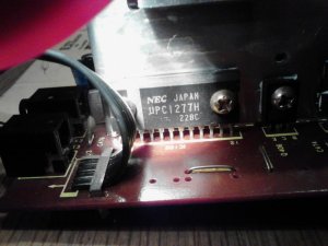
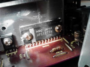
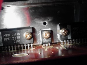
I took some pics of the amps, I didn't see any obvious damage or burns:

0127140653.jpg0127140654.jpg0127140654a.jpg
 

Superduper

Moderator
Staff member
On a C100, I once saw a melted module. On all the rest of the bad modules, I never ever saw any external signs of damage.

If you have a audio signal tracer, you can probe the input leads to the amps and can actually listen to the audio as it enters the amp. If no distortion in, but distortion out..... then bad amp is highly suspect. BTW, many BTL amp pairs criss cross the bridging meaning 1 bad amp module will affect both amp modules.
 

blu_fuz

Well-Known Member
Staff member
Now that a loving BBXery member sent me an original service manual I can really dive into this.


I ordered amp chips a few days ago and heat sinc compound just in case I find a problem with the amps I want to eliminate the problem right away.


I will check back when I find out more. Thank you!
 

blu_fuz

Well-Known Member
Staff member
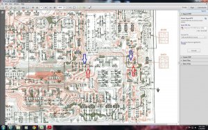
I had a little time to probe the traces from vias to vias following the red lines of the 5350 service manual.


If I am doing this correct, the blue-to-blue arrow should show continuity, and the red-to-red arrow should show continuity, correct?


One of those traces shows no continuity and my DMM doesn't do anything when checking resistance..... the other trace shows continuity AND very low resistance (like it should).

5350 arrows.jpg
 

Superduper

Moderator
Staff member
Your image shows too small on my screen for me to see anything worthwhile but generally speaking, the upper traces and vias are coated so it's hard to get reliable readings from them. Forcing your probe into the via risks damaging and introducing problems where none existed before. I would take a reading from the bottom side at the next closest solder pads from where those vias connect. Sometimes, it is easier to find the resistor or cap at that pad, and clip probe clips to the component leads from above.
 

blu_fuz

Well-Known Member
Staff member
Yeah I was trying to blow it up in the PDF, take the screen shot, open in paint, add the arrows, and attach it here. The attachments are just so small. You can click the img to make it bigger but those 2 red traces are easy to see.


I'll try the probe at the top side of the board to see if I can get some readings.
 

blu_fuz

Well-Known Member
Staff member
So I checked again. The red arrows, pad to pad (not with DMM probe in vias') beeps for continuity, but the resistance is coming in at about 18ohm.


The blue arrows, pad to pad (no probe in vias') is still reading no continuity and no meter reaction for resistance.
 

Superduper

Moderator
Staff member
blu_fuz said:
So I checked again. The red arrows, pad to pad (not with DMM probe in vias') beeps for continuity, but the resistance is coming in at about 18ohm.


The blue arrows, pad to pad (no probe in vias') is still reading no continuity and no meter reaction for resistance.
Because the printed traces are not copper but rather conductive paint of some sort, there is bound to be a certain amount of resistance and 18 ohms is not alarming but if you can't get continuity at the other trace, and you are sure they are supposed to be connected (you have the board and the only one able to get hands on access to it, so YOU are the man on the spot), then go ahead and jump those two points. If you can, see if you can find those two points (see next closest two components and ID to confirm on schematic. I would be interested to see where that break is in the circuit path. I always compare to the schematic before hard wiring a jumper just to make sure I didn't make a mistake following the trace pattern, which is easy to do.

I have seen several examples of double sided boards with bad traces on the painted side. As I said, this was PRE modern boards; today boards uses true copper foils on both sides (and sometimes, more trace layers sandwiched between too) and modern boards did away with the unreliable printed design.
 

blu_fuz

Well-Known Member
Staff member
I will double/tripple check that indeed is the printed trace I am following before jumping anything.


When/if I jump pad to pad do I need to incorprate any resistance into the jump wire or is a simple wire A-to-B ok?