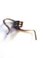
Seems the music wire is the correct torsion spring wire to use. The 1.2mm Diameter wire is a little too big and it is hard to make sharp corner bends. It would also be good to have a vice to hold the wire as one bent it. I only had long nose, pointed nose and big vice grip pliers to do the job. My picture is not very good as my phone is a cheap phone. This is the second spring I made. Actually, the first spring came out better. I also may have a problem with the inside diameter as it is only 3.65mm.This lazy technician had to check. So, the IC the music selector switch goes to is a Toshiba IC and the data sheet says the output is no greater than 150 mA so the switch will have no problem. Just order some torsion spring for the bottom tape door. Thank "caution" for the for his hard work on the specification on the spring.

Can anyone confirm what the Original Tape 1 door spring looks like on a Conion C-100F
I have seen a few different photos floating around. Is this what it looks like?www.boomboxery.com
Took a long to find anything close but this torsion spring outside diameter is 6 mm the Dia of the wire is 1.2mm it is music wire and right wound. They show the picture of it as 180 degrees but then say the deflection is 180 degrees. I do not think they know the difference. We will see when it comes in. I was leery of getting the stainless steel one as my experience with stainless is that once it exceeds its limit it factures completely. I am not sure how they make a stainless-steel spring, but I would imagine Carbon has to be added which might help the facture.
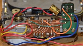
I have replaced 118 electrolytic caps, and I have about 26 more to do. I replace two belts on the lower drive and only have the upper and the counter belt to do. I cleaned the heat sink ICs and repasted them. still have to make sure the speaker that was coming in and out has a good reading on the meter and maybe connect and amplifier to it just to make sure.
I guess the correct way to bend a spring is by using heat and an oven to control the temperature. Then once bent one has to re-harden it again with a lower temperature.