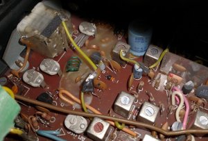
I am the original owner of a 1979 Sanyo M9998. I want to use it to feed my cassettes into a computer to digitize them. But first I have to get the box working.
Given what that has entailed so far I'm relieved to see even the experts are challenged by this one. Countless hours of struggling with it have taught me some tips to pass on. Which I will do below.
This site contains quite a few discussions of working on the M9998. So it isn't easy for people looking for guidance to find the most helpful. My post will add to the clutter, but I will add a link to here, on what I thought was the best of them:

 boomboxery.com
Edit: the older posts are no longer open for additions.
Getting the AM band to work properly is 1 of 2 remaining problems. I have overhauled the band selection switch. At full volume I get almost inaudible white noise from the speakers, and two very faint radio stations. FM works fine.
The other problem is the tape runs at about 80% normal speed. I can't find any mention of a motor speed control in the manual. The pinch roller is clean but slightly convex. I have a new one on order anyway.
Any assistance with these two problems would be greatly appreciated.
Given what that has entailed so far I'm relieved to see even the experts are challenged by this one. Countless hours of struggling with it have taught me some tips to pass on. Which I will do below.
This site contains quite a few discussions of working on the M9998. So it isn't easy for people looking for guidance to find the most helpful. My post will add to the clutter, but I will add a link to here, on what I thought was the best of them:
Operation Sanyo M9998!
Finally after a long wait I started working on my Sanyo M9998. From the way the PC boards are positioned in the unit I wanted to try the easiest way to reach the deck section. When I tried before it seemed really hard to reach the deck section. Today I found a much easier way to reach the deck...
boomboxery.com
Edit: the older posts are no longer open for additions.
Getting the AM band to work properly is 1 of 2 remaining problems. I have overhauled the band selection switch. At full volume I get almost inaudible white noise from the speakers, and two very faint radio stations. FM works fine.
The other problem is the tape runs at about 80% normal speed. I can't find any mention of a motor speed control in the manual. The pinch roller is clean but slightly convex. I have a new one on order anyway.
Any assistance with these two problems would be greatly appreciated.
Last edited: