Sanyo M9998 Restoration.

thinkchronicity

Member (SA)
Jul 5, 2018
176
33
28
Surrey, UK
Great to read your accumulated wisdom. I'm drooling over that Sencore - the last piece of kit i need is looking something like that. That book you linked to has been snapped up already damn..
I've got a few books on this subject. Pretty hard going when it gets to fm detectors and suchlike. My best buy so far has been some radio course books from the ICS correspondence schools circa 1978/80. They're so good i might scan them and put them up as a file here. IMG_20231220_124419_3.jpg

I don't have decades of experience, but it seems to me that for every old radio i've come across the station is never where it's meant to be on the dial! So i'm theorizing that when it comes to 'trim' components the top ones to go out would be trimpots (makes sense with wiper contact points degrading), followed by trimcaps (as just proven above), and then IF transformers (can't really see how these can drift considering their construction).

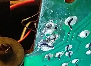
I'm with you in that i'm not into random tweaking. I've probably given the wrong impression though. So looking at the circuit again, i don't claim to follow everything, but i guess (AM) transistors Q301 & 302 are up for voltage checks, and diodes D105, 301 & 304 can have a diode checker on them. That's something a beginner can do with a multimeter before throwing in the towel. And touch up any dead looking solder joints with more solder.
 
  • Like
Reactions: BoomboxLover48

Superduper

Member (SA)
............... but it seems to me that for every old radio i've come across the station is never where it's meant to be on the dial!
Books dealing with AM/FM Stereo troubleshooting, when reasonably priced, disappear very quickly on eBay, especially if there's a link to a book posted in a forum thread.

You don't need an oscilloscope to do the band and tracking adjustments, but you really should get an RF generator. No wait, I take that back, you MUST have one to do the alignment. Honestly, these instruments are tons cheaper now than when I acquired mine simply because tuners nowadays have evolved and many are single chip tuners with no adjustment other than the 19khz pilot signal. The rest is all internal to the IC. Because of that, old school tuner alignment on traditional ganged tuners is slowly going the way of the dinosaurs. Therefore, there is a declining need for technicians to keep these on the bench unless they specialize in old school audio, and honestly, unless the ones they are using conk out and no longer repairable, it's probably the last unit they'll ever need if they have a decent one. Take one look at almost all radios these days... they are all electronic tuners, no ganged capacitors. Open up a car stereo, none of those coils or varicaps in sight.
 

SGrant

Member (SA)
Dec 9, 2023
38
1
8
Vancouver British Columbia
Update and trial #9

The new pinch roller arrived so I went to install it. The shaft bore is about 1.5mm while I believe I ordered a 2mm bore. So the new one won't install. Wonderful. I put the old one back. I removed the belts to clean any contamination off the motor belt that may have happened while it was misaligned. I then went to assemble the box enough to test it...

And found a spring laying on the table that had come out of the guts of the tape drive. These two setbacks were so depressing I had to stop working on it for the day.

I studied the diagrams in the manual and my photos, and figured out where the spring went. I also realized I could put the rubber portion of the new pinch roller on the old roller core, and did that. Assembled for testing.

The tape runs, and my untrained ear says it's running slightly slow. No wow and flutter. Maybe it needs motor lubrication or a thicker motor belt. So this is very encouraging. However for the first time the tape drive door latch does not work. So that has to be sorted out.

FM works fine. Sounds perfect. Same for all the sound controls except for slight scratching noise from a couple of the potentiometers. No big deal.

But no change with AM. The two signals I barely get, at maximum volume, are 1200 and 1550. Neither is sufficiently clear to get the station identification. I played with CT-4 and CT-5 a bit with no change. I know their original positions from photos. I did not yet go through AM Tuning steps 1-5.

If I can't get the AM working, it's not the end of the world since my primary concern is to use the tape drive. But the AM band is an interesting challenge and would add to the long term value of the box.

I was thinking that the ferrite aerial L106 could be tuned by altering the coils of wire around it. But I'm not contemplating doing anything like that.

Christmas wishes to you people doing so much for the community.
 
Last edited:

Superduper

Member (SA)
If your motor needs to rely on lubrication to improve speed, it won't last. The lubrication dries up very quickly. As you probably figured out by now, as much disassembly is required, lubrication of the motor simply isn't a feasible form of regular maintenance.

I have worked on many of these M9998's over the years, and I concur. It's a terribly frustrating experience. First of all, every example that I've worked on had slow tape speed. Ordinarily, you would just adjust the speed control and be done with it, but as you've discovered, there is no speed control for this set. Also, like you, it seems every time I reassemble it, I discover a step that I forgot, a misrouted wire, or unable to button up because wire looms can't fit back where they were making it impossible to button everything up together, or a misconnected lead... always something. The point is that your experience is nothing unusual. It's par for the course on M9998s.

AM reception on this era of Sanyo radios either have a poor design or choice of components that degrade. They seem to always have tuner issues, AM is no exception. In most of the cases that I've experienced, it's due to failing or failed components. Even if an alignment can set you back closer to where you need to be, the only reason for alignment drift is failing components. This I tried to mention to you before. As you've discovered, tweaking the controls didn't fix it, and now that those controls are tweaked, if it didn't require an alignment before, it certainly does now. Even if the diode or transistor or capacitor that is causing the issue is replaced and resolved, a full alignment now is highly recommended. Those little screws are remarkably finicky. It may not be apparent by ear, but typically, when you tweak a control with an instrument hooked up, you can see how difficult it is to get them dialed in perfectly. It often seems like you can get different readings on the instrument even with the adj screw set to what seems like the exact same spot. I'd leave it alone right now until you figure out what is causing your dead or weak AM. The fact that you can't get a strong enough signal to even identify it tells me that it's definitely not an alignment related issue. Once again, there are youtube videos out there that show you how to use a small AM radio to check if your local oscillator is functioning. If functioning, the oscillator generates a signal that can actually be tuned into by a nearby AM radio (hence the use of a portable). If you try this test and the results suggest a failed OSC, then you can certainly try to replace the oscillator or mixer transistor.
 

SGrant

Member (SA)
Dec 9, 2023
38
1
8
Vancouver British Columbia
I've gotten pretty good at arranging the wiring properly and putting the many different screws back in the right places without using my own instructions. I've labelled the connectors and where they go. I've learned to get the record mechanism and piano key parts arranged properly. I'm making sure no wires press against the motor and cause belt misalignment. But new mechanical issues just keep happening. I'm also concerned wires can only take so much repeated bending.

Would the fact my twiddling did not cause a change in the AM reception indicate I may not have misadjusted something?

My main goal was to use the tape drive to feed an analog signal to a computer to digitize my cassettes. It occurred to me that digitizing software, like Audacity, has a feature to adjust recording speed. Theoretically I could use the tape drive as it is and get a satisfactory result by using the software to correct the speed. Maybe.

I'll look into the AM radio experiment you suggested.
 

Superduper

Member (SA)
Every tape you produce with this tape deck will probably play back at the correct speed since record and playback speeds will probably be the same, but it will only play correct for this deck. So you don't need any software, you just need to record your own tapes.

When your tuner is not working properly to start with, with virtually no stations coming in (the 2 you captured might not even be actual stations that you would receive in the normal manner, but they could be ghost signals amplified by the AF section. Therefore, you can't know with any certainty whether alignment has been compromised. In my experience, it might remain close enough for you to be satisfied with it. This is AM after all. Even if the tracking is slightly off, it probably won't be objectionable, but not objectionable isn't the same as correct.
 

thinkchronicity

Member (SA)
Jul 5, 2018
176
33
28
Surrey, UK
Well done. It can be emotional high risk, all the hours spent. But the flipside is when it doesn't work....you're in the mystery school...a place of high learning.
So great, we've eliminated (front end) tuner alignment as the issue, with relatively no harm done i hope. Ct-5 should have been left alone - that only alters the frequency coverage limit - but not a big deal.
I've recently brought two AM radios back to life from dead, so your problem is annoying me.
Can you check the collector voltage on Q301 and 302 sometime? Q104 too. Should be around 7.3v. And test the diodes i listed earlier if your meter can do that. Looking in my Homer Davidson book under 'no AM - FM good' it says: INSPECT THE AM ANTENNA COIL FOR A BROKEN CORE OR WIRE CONNECTION. Then goes on to mention testing the transistors above.
 

thinkchronicity

Member (SA)
Jul 5, 2018
176
33
28
Surrey, UK
Actually Q104 is the prime suspect here. It's the osc./converter transistor. Check all its voltages first. I think Q301/302 are shared IF transistors, so if FM works so do they.
 

SGrant

Member (SA)
Dec 9, 2023
38
1
8
Vancouver British Columbia
I tried the AM radio test. I was unable to get the squealing interference feedback with any combination of frequencies. But, the box's AM would act as the tuner for the portable, causing the portable to emit the range of stations as the box's tuner was dialed. And at the high end of the range the portable would cause one station to come through on the box when they were tuned to the same frequency.

More definitive, the voltages on Q104 were: B 6.44, C 0.0 and E 1.59. Whenever I touched the vom lead to the base lead, the box immediately was broadcasting a station, loud and clear. These were tested to ground on the band selector switch case.

I checked Q104 again later: B 6.4v, C 0.012v, E 7.6v. And a third time: E 7.6v. Maybe I misread E the first time.

In case this is the smoking gun, I didn't check the other transistors mentioned.

The AM aerial ferrite rod is intact and the wiring appears to be unbroken and connected.

As for the motor, the speed is sufficiently accurate that I can only notice a problem at the higher mid range. My hearing isn't good enough to hear frequencies above about 10khz. I won't be recording cassettes on it to play back. I'll only be using the unit to play cassettes already recorded. It would seem replacing the motor makes more sense and is easier than lubricating it. I haven't looked into how difficult it will be to find a compatible motor. At least, according to the diagrams, the pulley is removable.

The AMSS works as it's supposed to. The earphone jack works fine. I haven't tried recording yet.
 
Last edited:

thinkchronicity

Member (SA)
Jul 5, 2018
176
33
28
Surrey, UK
Hmm. This is a learning curve for me too.
Are you sure the collector and emitter readings are the right way round?

Are you saying when you touch the VOM lead to the base the AM radio works perfectly across the band?
 

Superduper

Member (SA)
I don't believe your measurements, lol. Make sure you are assigning the BCE leads correctly. Also, you are referring to the correct service manual right? Not the K version or the LU version right?

Also, your probe could be acting as an antenna. Or if the transistor lead has a poor solder joint, putting pressure on it could restore connection.
 

SGrant

Member (SA)
Dec 9, 2023
38
1
8
Vancouver British Columbia
I went by the "B" and "E" printed on the PCB. The service manual is for the M9998 (USA). I got one radio station whenever I touched the lead to "B". I didn't move the tuning dial to see if I could get any other stations. I will try once again to look up how transistor contacts are labelled and how the arrangement corresponds to the transistor symbol. So far the results have been ambiguous which is why I went by the PCB markings.

Incidentally, in this photo you can see some sort of deposit on the top of Q101. I wasn't aware transistors can leak, so probably it doesn't mean anything.

IMG_20231223_190643116~2.jpg
 

SGrant

Member (SA)
Dec 9, 2023
38
1
8
Vancouver British Columbia
According to the circuit diagrams, Q101 indeed is in the FM portion. As Q104 also appears to be. Although Q104's Emitter seems to connect into the AM section.

Q301 appears to connect to S101-3, which is an AM selection on the band switch. I have to find components on the wiring diagram in order to locate them on the PCB. It took me a while to find Q301 on the wiring diagram because it is mislabelled as Q309. I hardly need that sort of confusion.

Voltages on Q301 as marked on the PCB are:
B: 6.4v, C: 0.00v, E: 7.15v
The B and E as marked on the PCB may be reversed and refer to looking at the pinout from above instead of below, or below instead of above. I have yet to settle in my mind what the convention is.

According to the wiring diagram the voltages on Q301 are supposed to be:
B: 1.31v, C: 7.13v, E: 0.65v

And I just found rewind on the tape drive grinds to a halt. Play also slows toward the end of 90 minute tapes when the effective gearing is the worst. And stops before the side is done. If I remove the cassette bay clear panel and run Play without a tape, the take-up reel and capstan/pinch roller seem to be very forceful. And the "supply" reel has minimal resistance. So I don't know what's triggering the "end of tape" stop. Most commercial artist tapes are shorter and don't have a problem.
 
Last edited:

thinkchronicity

Member (SA)
Jul 5, 2018
176
33
28
Surrey, UK
To dispel your confusion look up the transistor number (the long one) in the list of components for Q104 in the manual. Find the datasheet online - it will give the pinout on the legs.
One thing i noticed: the selector switch position on the schematic is at FM not AM. So can you switch to FM and re-measure the voltages on Q104.
And when that station comes thru loud(on AM) when pressing the base....have a tune around the band!
 

SGrant

Member (SA)
Dec 9, 2023
38
1
8
Vancouver British Columbia
Hello again.

During my absence I was repairing multiple problems on two Aiwa HS-J09's. They have just one problem left out of about 4 each (reverse play does not work on one of them). So back to the M9998. While it's nice to be working with parts larger than gnats, the M9998 is an awful tangle of wires and parts.

To review, the M9998's AM band was not working, and the now-working tape drive had lots of w&f and slows to a stop.

I have not yet gone back and done some of the tests suggested. For example, seeing if my voltage checks were done with or without the band selector switch on AM. And investigating why I suddenly got radio reception when checking voltage on a component. I may yet need to do that.

What I learned working on the Aiwa's led me to a different approach. Most problems other than the rotten belts were broken wires connections. So now my prime suspect for the silent AM band was a possible broken connection near the AM antenna. The first thing was to use the circuit diagrams to locate what components the AM pins on the S101 switch connect to first. Then do resistance checks.

All S101's AM pins showed connectivity except 3. So far I haven't found a place to access the two circuits from S101-3. I found no conduction between S101-6 to C323. This is supposed to connect the antenna to the mixer/converter section. But I'm not 100% sure I had a good probe contact at the capacitor.

About that time I noticed a broken solder blob. This blob connects one end of the fine antenna coil winding wire to VC-1-5 and CT-4. I have no idea how such a solder blob could have fractured, and fixing and testing it awaits dealing with the tape drive issue.

Which is the belt/capstan speed. I removed the motor. Its spindle rotates freely with the only resistance coming from the faint pulsing from the windings.

I don't know how a motor like this one would feel if it was shot, and my guess is it spins too freely to indicate a need for lubricant. You can give it a good spin and it "coasts" for a while. I guess the next step is to examine the tape transport assembly to find where there might be drag or friction.

My original goal in fixing this unit was to use it to digitize my cassettes. But now I can do that using the Aiwa's. So fixing the Sanyo has become an end to itself.

IMG_20240226_190805187_HDR.jpgIMG_20240226_190805187_HDR~2.jpg
 
Last edited:

SGrant

Member (SA)
Dec 9, 2023
38
1
8
Vancouver British Columbia
The resoldered connection didn't fix anything.

From working on the Aiwa walkman, I realized the cassette I was using for testing them and the Sanyo, does not turn freely. Just before trying a known good cassette in the Sanyo, I put a drop of WD-40 into the spindle end of its motor. Other than that the motor seems completely sealed.

I don't know which of these two changes was the solution but the cassettes run fine now.

Back to the AM band.

When I touch one vom probe to ground and the other probe to pin labelled "B" on transistor Q104, and with the band selection set to AM, it plays and dials AM stations as normal. Touching the probe to a few other places adjacent in the circuitry did not play any AM. It didn't matter if the vom was turned on or off.

I tried using a jumper between Q104 - B and ground. No AM.

I tried the vom again. I get the AM band fine with a probe on ground and the other probe on Q104 - B, but nothing if I reverse the probes. So is the vom acting as an antenna, but only if it is arranged one way?

I checked the voltages on Q104:
B - 1 (plus the audio)
E - 1
C - 0

They are supposed to be:
B - 7.33
E - 0.54
C - 1.14
 
Last edited:

thinkchronicity

Member (SA)
Jul 5, 2018
176
33
28
Surrey, UK
I don't know which of these two changes was the solution but the cassettes run fine now.
[/QUOTE]
Hmm....i think i know!

The am thing points to a bad solder joint on the base surely. The vom can't act as an aerial - this is not fm.
 

SGrant

Member (SA)
Dec 9, 2023
38
1
8
Vancouver British Columbia
Even stranger...

The vom set to measuring voltage, and connecting Q104 B to ground, produces AM reception only with the red probe on ground. Not with the black probe on ground.

But if I set the vom to measure resistance, I get AM reception with the probes both ways around. I don't know anything about how vom's are wired, so I have no idea why this is so.

I repeated these trials, with 100% consistent results, too many times to consider a loose joint on Q104. But I will poke around on it.

If I just hold something metal against Q104 B, I get loud buzzing with a radio station that is not as loud as the buzzing. So it seems I was acting as an antenna.

Enjoying listening to cassettes on the box. I might just have to hook it up to my external speakers, and get a forked cable to plug other devices into the microphone jacks.
 
Last edited: