Sanyo M9998 Restoration.

thinkchronicity

Member (SA)
Jul 5, 2018
176
33
28
Surrey, UK
These two remaining issues are small in the scheme of things, but toughies to crack. Just wanna say don't give up! I know you've spent many hours already on your grail box, and it will be so worth it.
You mentioned earlier the pinch roller was slightly convex. That's healthy and normal. You might want to hold off replacing it unless it's misshapen, cracked or rock hard.
As Superduper says belt tension is critical. Too much and everything's going south on speed. Be suspicious of any belt's dimensions no matter who supplied it. And no matter what the PRB belt guide said.
I hope you can figure out a way of testing while powering the thing. I know this can be a real headache. One tip: while a board is out you can solder long wires to the test points you normally can't reach when it's all back together again.
 
  • Like
Reactions: SGrant

SGrant

Member (SA)
Dec 9, 2023
38
1
8
Vancouver British Columbia
Today's update.
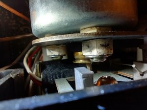
I found the motor belt was not positioned correctly on the motor spindle.
IMG_20231213_152812366_HDR.jpg


Running on the larger diameter part of the spindle next to and rubbing on the motor plate would cause the tape to run slow. I haven't put the unit back together to test it yet, so I don't know if this involves the progressive slowdown during play. I admit to an own goal.

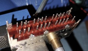
I took the band select switch off again. I figured that since it mounts with a gap between it and the board, there is room to use zip ties around it to hold it together if the case clips break off.

The switch has two rows of electrical pins, in sets of 3, 4, 4, and 1. They don't have numbers assigned to them, so I'm calling them 1-12 starting with the set of 3. When I test them for resistance I get the following connection combinations, same for both rows of 12 pins:

AM: 3-4, 7-8, 11-12
FM: 2-3, 6-7, 10-11
FM AFC: 1-3, 5-7, 9-11

Edit: if I count the positions that don't have external pins, the numbering would be:
AM: 3-5, 8-10, 13-15
FM: 2-4, 7-8, 12-13
FM AFC: 1-3, 6-8, 11-13

The pattern doesn't fully make sense to me, but the pattern suggests all contacts are being made, for now. It seems to me that if this arrangement is incorrect, and I reposition the slider either way with respect to the gear (and knob), a connection at either end of the range will be lost. That there are a couple of barely audible AM stations suggests the switch is ok. Unless high amplification is picking up stray frequencies

When I open up the switch to clean up the dielectric grease, I'll check to see if there are asymmetries I haven't noticed before.

It appears the AM tuner has only 2 electrolytic capacitors:
C303 electrolytic 10uf 16v
C323 al electrolytic 0.1uf +40-20% 10v

Both of them look ok, and checking their voltages would be a challenge. The idea of installing long leads is brilliant.

A new pinch roller is on order, so it'll get that. The best thing about this work, besides the help available, is that parts are so cheap.
 
Last edited:

thinkchronicity

Member (SA)
Jul 5, 2018
176
33
28
Surrey, UK
Yep, been there done that with the belt!
I'll let Superduper come back to you on the switch info.
The fact that FM works well means that all those transistor sections are working too, i think in hindsight. Those two caps could come out for testing. An esr meter would be handy, but a capacitance test to start with anyway.

One thing you could try tweaking : on the polyvaricon tuning capacitor there are 5 trim caps. On the schematic they're labelled CT1 thru CT-5. CT-4 is the AM RF trimmer - it hugely affects the signal strength that is passed on to the next stage. It only turns half a turn in its active range, then you can carry on turning but its just a repeat of the previous half turn as the semicircular vanes (or plates) intermesh and then separate.
So, in tiny print on the tuning cap the five trimmers will be numerically indicated. Find no. 4 and trace the wiring to the nearest component(s) on the board and check with the schematic that no.4 is in fact CT-4. You don't want to turn the wrong one.
Then tune to that weak station and have a twiddle.
 

thinkchronicity

Member (SA)
Jul 5, 2018
176
33
28
Surrey, UK
Looking at the pcb wiring diagram for the radio: the 30 pin switch - above where it says COM & AM there are two triangles labelled 4 & 5. Are those jumper wire connections? Just curious.
 

SGrant

Member (SA)
Dec 9, 2023
38
1
8
Vancouver British Columbia
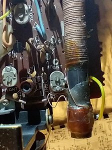
C303 has a very small ceramic capacitor glued to the top of it. I have no idea if removing the ceramic one has any consequences. Such is my lack of experience.

I think I have located CT-4. I don't see any numbers on it though. I'll play with it and report back.

IMG_20231214_111215838_HDR~2.jpg
 

SGrant

Member (SA)
Dec 9, 2023
38
1
8
Vancouver British Columbia
From a post above, regarding the band selector switch. Editing the post has timed out.

"The switch has two rows of electrical pins, in sets of 3, 4, 4, and 1. They don't have numbers assigned to them, so I'm calling them 1-12 starting with the set of 3. When I test them for resistance I get the following connection combinations, same for both rows of 12 pins:

AM: 3-4, 7-8, 11-12
FM: 2-3, 6-7, 10-11
FM AFC: 1-3, 5-7, 9-11

Edit: if I count the positions that don't have external pins, the numbering would be:
AM: 3-5, 8-10, 13-15
FM: 2-4, 7-8, 12-13
FM AFC: 1-3, 6-8, 11-13

The pattern doesn't fully make sense to me,"


It makes more sense now. There are gaps between the groups of pins where pins are truncated. I wrongly thought that eliminated them from the picture. They have connections that probably are redundant. Including them, the connections now are:

AM: 3-4, 3-5, 4-5, 8-9, 8-10, 9-10, 13-14, 13-15, 14-15
FM: 2-3, 2-4, 3-4, 7-8, 7-9, 8-9, 12-13, 12-14, 13-14
FM AFC: 1-3, 1-4, 3-4, 6-8, 6-9, 8-9, 11-13, 11-14, 13-14

IMG_20231214_113552521~2.jpg
 

thinkchronicity

Member (SA)
Jul 5, 2018
176
33
28
Surrey, UK
Not so fast. CT-4 is located on the clear plastic 'box' with the yellow and brown wires going to it. In other words the tuning cap you took a pic of earlier.

The extra cap in parallel is probably a minor afterthought they added. You can leave it attached for testing purposes. Do you have a cap meter?
 

thinkchronicity

Member (SA)
Jul 5, 2018
176
33
28
Surrey, UK
So dividing up the pins as orientated in your pic into six groups of 5, as in the pcb schematic, when AM is switched then pins 2 & 3 (reading left to right) in each of the six groups should be connected. I'm not using your numbering system. If you have an ohmmeter then test all those connections which should be shorts. Just because you're getting a tiny signal doesn't mean the switch is ok. It could be making the connection, but with a high resistance contact, so attenuating the signal.
Check this before fiddling with ct-4.
 

SGrant

Member (SA)
Dec 9, 2023
38
1
8
Vancouver British Columbia
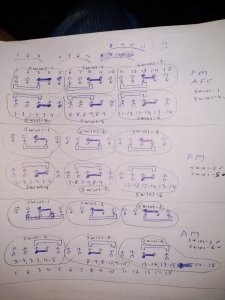
I'll attach the diagram I made of S101 band selector switch.

Inside the S101, pins 3-4 on each of the two rows are connected to the same piece of metal the associated "slider" touches. Same for pins 8-9 and 13-14.

According to the schematics, SW101-4 is accociated with FM AFC. There is no representation for SW101-1 on the circuit diagram. I speculate that when the switch is in the FM AFC position, the non-common pins connected by the other sliders are not connected to anything. Same for FM and AM.

SW101-2 and 5 are associated with FM.

SW101-3 and 6 are associated with AM.

The consistency and logic of the connection pattern suggests the contacts are in proper shape.

The vom goes to zero on the active combinations of pins. I cleaned whatever lubricant was in the switch, applied DeOxit D5 and put it back together. Not remounted yet.

I don't have a cap metre and have never measured capacitance. No problem to look it up.

The polyvaricon capacitor has nothing on it to adjust, anyway.
IMG_20231214_170711878~2.jpg
IMG_20231214_170632541.jpg
 

thinkchronicity

Member (SA)
Jul 5, 2018
176
33
28
Surrey, UK
Ha, i knew i shouldn't have got involved with the switching! Ok delete my last post. The schematic didn't show the shape of the slider, but now i get it. Never had one of these apart myself. SW101-1 is shown btw on the schematic next to L106 the ferrite rod.
Time to give CT-4 a tune up.
 

SGrant

Member (SA)
Dec 9, 2023
38
1
8
Vancouver British Columbia
SW101 is a clever device. FM and AM modes each connect 6 contacts to common. FM AFC adds 6 contacts to the FM contacts. I don't know how many of the contacts are not used, but it must be a lot of them. And I don't know enough to figure out where most of the used contacts go to.
 

Superduper

Member (SA)
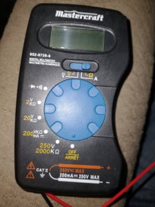
Someone please explain to me WHY are we fooling around with CT-4? Tuner alignment and repair is a very exacting science, not to be fooled with blindly. It seems like you guys are just shotgunning blind without any sort of troubleshooting plan or process. From the looks of it, you likely have a service manual. NOTE that AM alignment is a 5 step procedure where you go through the steps 1 at a time, and then repeat. The reason why is that each step affects the next, and to a lesser extent, the previous step. So with each cycle, you get closer to and narrow the amount of adjustment. Tuners don't just go out of alignment for no reason. This could be a case of a weak oscillator which could be a circuit issue. GO to the service manual AM alignment chart and review the steps. IF you decide to attempt it, you should do it in steps 1-2-3-4-5-repeat. Messing with C-4 which is the very last step in the process and therefore makes no sense to start there, and suggests this is just a blind exercise of tinkering. If you get it hopelessly out of wack, you might might never be able to get it back again without professional help. The service manual is there to guide you, use it, don't ignore it. BTW, step 1 for the IF adjustment requires a signal generator and an oscilloscope. If you have neither, you can just cross your fingers and hope that setting is correct and proceed with the other 4. A high quality 20m ohm DMM probably will work, although the one you showed I'm not familiar with and it looks rather basic.
 
  • Like
Reactions: SGrant

thinkchronicity

Member (SA)
Jul 5, 2018
176
33
28
Surrey, UK
Messing with C-4 which is the very last step in the process and therefore makes no sense to start there, and suggests this is just a blind exercise of tinkering. If you get it hopelessly out of wack, you might might never be able to get it back again without professional help.
I hear you Superduper! I haven't done a full IF alignment it's true, but i have spent a few hours messing with the tuner cap trimcaps on a couple of units to find out what they do in practice. And that's from a standpoint of knowing which is which and knowing the theory behind them. Our friend here won't be able to do a full alignment, so if my idea falls flat then he'll need professional help anyway i should think. As you say it's the last in line to be adjusted, (which makes it the ideal candidate to adjust on a beginner 's level), and if it was badly out of whack then it could explain the symptoms here.
It's a discrete component not enclosed in the usual protective polyvaricon housing so maybe it's more prone to drift.
 
  • Like
Reactions: SGrant

Superduper

Member (SA)
Here's the thing; you should be logical in the approach to repairing things. The steps prescribed in the service manual is there for a reason. The IF adjustment needs to be correct, otherwise the other adjustments just won't work and you may in fact just needlessly throw things out of wack.

For example, your car is bucking like a wild pony. You suspect that the transmission needs adjustment so you are thinking of tweaking the valve body or the solenoids, transmission vacuum modulator etc. When in reality, the engine has a terrible surging issue. IF you don't fix the engine and tweaked the transmission, the issue is not fixed but the transmission is now out of wack to where even if the engine is fixed, the car still won't run right.

Additionally, it's probably more important to know if the oscillator is even working. If not, fix the oscillator circuit and the tuner magically works again, without any adjustments. Then there's CT-4 adjustment... why are we messing with that? It's not rhetorical, I mean, it's a real question. A weak tuner is NOT the reason to adjust that, because that (step 5) and (step 4) are for bandwidth adjustments. You will notice if you read the adjustments carefully that step 4 adjusts the low end and step 5 adjusts the high end. In other words, if your tuner tuner needle is at 1350 but you are receiving a station at 1410, then the band adjustment is wrong. Or if your tuner can only tune from 690khz to 1710khz when it should tune from 550khz to 1650khz, THEN the steps 4/5 should be performed and repeated until the correct range that the tuner is capable of is attained. Those adjustments WILL NOT improve signal strength, it only shifts where the signal is received in relation to the tuner dial scale. So once again, is the problem that the tuner is not tuned to the proper spot in relation to the dial scale? OP didn't say that I don't think. But then again, he didn't really specify if the 2 stations he received is in the correct spot.
 
Last edited:
  • Like
Reactions: SGrant

thinkchronicity

Member (SA)
Jul 5, 2018
176
33
28
Surrey, UK
A weak tuner is NOT the reason to adjust that, because that (step 5) and (step 4) are for bandwidth adjustments.
Sorry, but that's not correct. Steps 2&3 set the bandwidth limits - the oscillator adjustment.
Steps 4&5 are the AM tracking or RF adjustment. This strongly affects signal strength especially at the top end of the dial, hence the high frequency input specified if you're doing it strictly by the book, and you have all the tools. In the UK the strongest stations are in the high end, so i'm assuming those 2 our OP can pick up are similarly placed. Which makes adjustment of CT-4 a reasonable choice for quick experimentation. As always a mark in pen of its original position should be made before turning, but given the active range of these is only half a turn before it repeats (if you keep turning), then you can't get too lost.
It would be helpful to know if those two stations are in the right place on the dial...
The manual at step 4 gives L106 as adjustment for the low end signal strength of the AM band, but that's the fixed ferrite rod antenna....so not sure what they expect us to do there!
I agree that IF and osc sections are also under suspicion, but those are probably outside of our OP's scope to investigate.
There is a logic to my madness.
 
  • Like
Reactions: SGrant

Superduper

Member (SA)
I've collected audio equipment for over 4 decades, and to a lesser extent, began restoring them when my collection grew and I realized that the cost of farming them out to repair everything just wasn't sustainable. I've always strived to do things the right way, so I've not had as much experimenting with turning a screw just for the sake of seeing what it does. If that's your thing, go at it and carry on! Maybe you'll get lucky which admittedly, sometimes does happen. But I like to take a more methodical approach.

I also have a whole library of books, many on tuner and receiver theory. The book by Robert Goodman AM/FM Stereo system troubleshooting is highly useful, and contains sample or recommended equipment. I was so inspired by it that I've purchased over the years many of those same equipments that was shown there including 2 of the Sencore SG165 stereo generators, before later acquiring much more sophisticated lab grade signal generators that today would costs probably $20,000 each +. Luckily retired lab grade equipment can be purchased for cheap (by comparison). For someone wanting more info on this book, you can google it and there's also one on eBay: https://www.ebay.com/itm/145340798631. This book is even better but it's also a lot more costly if you can find it: THEORY AND SERVICING OF AM, FM, AND FM STEREO RECEIVERS - Green. Once you get into reading these books, you'll quickly learn that it is far more difficult to grasp this concept and that audio systems are by comparison far more elementary.

So over the years, I've accumulated the RF signal generators, oscilloscopes, audio generators, marker generators, signal tracers, etc. I've aligned dozens of tuners and if there's one thing I've learned, it is that you simply can't do it blind. You'll understand once you begin doing the alignments with these tools, you'll wonder why would anyone ever want to attempt the process without them. I would use this analogy. Anyone old enough to remember tuning up classic cars with a timing light and dwell meter will understand that yes, you can adjust dwell, and yes, you can adjust timing without benefit of either the meter or timing light. AND the adjustments do make a difference. But if you do it first by ear or feel, and then follow up with the actual tool, you'll find that the setting you thought was "correct" virtually never is. Can you adjust the carburetor by "ear" without a sniffer? Yes, but if you are in CA, you'll probably fail the smog test.

Regardless, I've learned over the years is that tuners rarely ever just go out of alignment, typically a failed or degraded component is the cause of the complaint. One book I read stated that the author always suspects the oscillator amp first on AM radios because 85% of the time, transistors are the component that fails. I don't know where he got that data from, but it sounds like it's from his personal experience servicing lots of radios. Regardless, I try to discourage randomly messing with tuners because the cause of no or degraded tuner performance is usually a component related issue, not an alignment issue, and I hate to see a properly aligned tuner get knocked out of wack by random tweaking when the cause is a failed transistor, diode, or broken IF transformer wire. If you really want to try tweaking because you don't want to hire a professional, or don't want invest the cost of getting these tools necessary to do the job properly, then there is a way to sort of test the local oscillator simply by placing another AM radio nearby. I won't go into the process because you can google the method yourself, and there's youtube videos showing how. But if you have another radio, a simple handheld is fine, as long as it is working properly, it can be used. I guess I've said what I want to say on the matter, so good luck with the repair.

I suggest that if you have lots of boomboxes and tuner repair is something you may be interested in playing with, at least get yourself a Sencore SG165. It includes AM and FM signal generator, stereo generator, 455khz and 10.7mhz output as well as 67khz Subcarrier, 19khz pilot signal, even includes 10.7mhz with markers.... what more do you want? Stereo separation test? Got it. Power output meters? Got it in 10W and 100W ranges. Basically, it's the perfect boombox test tool, all in one tester. Ok, it's not exactly, cheap but for 1/4 the cost of an M90, and less than the cost of a decent M70, in my opnion, why collect all the boomboxes and not get the one tool that's going to keep them running in tip top shape? The only downside is that there are lots of probes needed to use all the functions and these testers often are missing them. An even better version is the Sencore SG80, unfortunately that one is far more pricey and almost never seen anymore. Anyone that has one often won't offer them, they are keepers in their equipment arsenal until they retire or die.