Newly obtained Sanyo m-x960k!!!

Status
Not open for further replies.

Tinman

Member (SA)
Interesting, I never had a 960 so I didn't know it had a panel speed/pitch control.
That's one of the things I love about the SCR-8s, a simple hole to access the speed control.
I drilled access holes in both of the GE 5268s I own.
The motor is right behind the battery compartment so it works great with a relatively short screwdriver.
 
  • Like
Reactions: Jboulukos

Jboulukos

Member (SA)
Like I said, those two wires went to speed control terminals on the old motor. That's above and beyond the adjustment on the back of the motor.
Until you get a four-terminal motor, the pitch control knob on the front of the box is unusable.
Great insight. I didn’t think of that! Actually this is the first time I’ve ever had a vintage piece with pitch control. I’d love to get that working in the future. I’m going to prioritize the repairs. First it’s the speaker wire which seems like an easy fix. Next, and most important, is the low volume issue with cassette playback. Might need a new head, and I’m sure I can solder it but don’t know where to get one that fits this system.
If I can fix the first two things, then I’d be looking to fix the pitch control/white and blue wires/different motor set up. I get boomboxes very cheap where I live in South America but sometimes they are really messed with. For example, it’s common to see incorrect screws, broken tabs on cassette mechanisms, missing springs, and so much more.
Again, awesome info. Besides a new head, is there anything else I can check/clean/replace to attempt to fix the low cassette playback?
 

Jboulukos

Member (SA)
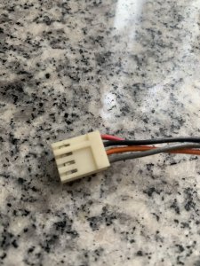
Undo the wires from the plug so you can bend the part that contacts the male part of the plug better.
They usually have a small tab in the open part of the plug that you press on with a very small screwdriver, toothpick, etc. then the wire pulls out from the plug.
After bending the contact point, bend the small tab back up slightly ( I usually use a razor blade) and push it back into the plug to lock it in.
Do all four the same way.
Push the metal contact for each wire downward/inward toward the plug?
A9A69D5F-4BF2-423A-A69B-4D7A811A68CF.jpeg
 

Jboulukos

Member (SA)
After pu
Undo the wires from the plug so you can bend the part that contacts the male part of the plug better.
They usually have a small tab in the open part of the plug that you press on with a very small screwdriver, toothpick, etc. then the wire pulls out from the plug.
After bending the contact point, bend the small tab back up slightly ( I usually use a razor blade) and push it back into the plug to lock it in.
Do all four the same way.
After bending the contact point inward, all 4 wires came completely out of the female end of the plastic plug. I lifted up the tabs and pushed each wire back into the plug, with the wires still moving loosely inside the female end of the plug as they previously were. Plugging it in did not result in consistent sound from the speakers. This plug seems like a hell of a poor design. I inspected a different plug and the wires and contact points do not move inside the female end. This plug seems loose or the wires have too much play inside the plug because they definitely move and rotate slightly. If the actually wire touches anything lightly, the pressure is enough to cause an issue with the connection to the speaker.
Other plugs I’ve examined do not do this…The contacts remain stationary inside the female end of the plug.
Is there any way to fix this so I can have consistent speaker function?
 
Last edited:

Tinman

Member (SA)
It doesn't sound like you bent the actual metal contact points of the female part of the plugs inside of the plastic plug shown in your pic above.
You have to bend them so that when the metallic male part of the plug (the part soldered onto the board) pushes into the plastic plug shown in your pic above, they make good contact.
The little tabs are only to help retain the wires into the plastic part of the plug.
Hopefully, that makes sense.
 
  • Like
Reactions: Jboulukos

Jboulukos

Member (SA)
It doesn't sound like you bent the actual metal contact points of the female part of the plugs inside of the plastic plug shown in your pic above.
You have to bend them so that when the metallic male part of the plug (the part soldered onto the board) pushes into the plastic plug shown in your pic above, they make good contact.
The little tabs are only to help retain the wires into the plastic part of the plug.
Hopefully, that makes sense.
I did all of the above and more to my understanding. I even tried ditching the female plastic plug and putting each of the 4 wires onto each of the 4 posts. They don’t stay. They don’t really fit. The female ends aren’t cylindrical. Please elaborate on bending. I bent the tab upward then inserted the free wire back in. I also squeezed the female end of each wire so that it would be tight around each post. The tab cannot be bent upward while in the female plug because the plastic valley block any tool from getting inside.
also, You can bend them anyway you want, they still move around and rotate slightly. They are loose. The other plugs do not exhibit this looseness. Not certain where to go from here on this. The plug seems like it’s not wanting to hold the wires still from the female end.
 
Last edited:

Jboulukos

Member (SA)
Bent ends of the wire to contact the posts and now the right channel is completely out and treble from the left side. This doesn’t seem like it’s working the wires are still very loose and this is making it worse. Any other input?
 

Tinman

Member (SA)
What I meant was when you had the wires out of the plastic plug, the part that you pushed onto the posts need to be bent slightly so that when they're back in the plastic plug and inserted onto the posts they'll make better contact than they were.
It's very easy to do, you might be over thinking it.

As a last resort, you could also do away with the plug altogether and either solder the wires directly to the posts or do away with the posts and solder the wires directly into the board where the posts go through.
It's not a great solution since you'd loose the ease of unplugging them in the future but the connections will be solid.
Also, you might want to verify that the 4 posts solder connections onto the board aren't cracked/loose which would also cause the problems you're having.
 
  • Like
Reactions: Jboulukos

Jboulukos

Member (SA)
What I meant was when you had the wires out of the plastic plug, the part that you pushed onto the posts need to be bent slightly so that when they're back in the plastic plug and inserted onto the posts they'll make better contact than they were.
It's very easy to do, you might be over thinking it.

As a last resort, you could also do away with the plug altogether and either solder the wires directly to the posts or do away with the posts and solder the wires directly into the board where the posts go through.
It's not a great solution since you'd loose the ease of unplugging them in the future but the connections will be solid.
Also, you might want to verify that the 4 posts solder connections onto the board aren't cracked/loose which would also cause the problems you're having.
Nice! Yeah, I’ve decided to resolder the posts. I feel I did what you’ve described but it must be the solder joints at the posts now. I don’t plan to fix the cassette player any more than I have already so I may need to solder one of the wires to a post since the little tab broke off and it does not stay within the plug anymore. First I’ll solder the 4 posts again. Then I’ll bend the wires again to see if I can get them to stay and if it fixes the sound. I’ll do this tomorrow. I’m hoping it works. I just want to use the phono function fir this unit since the sound is better than my other Sanyo. The boomboxes I get where I live in South America definitely have been messed with over the years.
 

JIm

New Member
Update:
I pushed the tab in the photo and it engaged the head. Play works now! Now speed adjustment. I have a cassette to calibrate the speed. Something I noticed on my deck is the white and blue cables are cut and not attached to the motor. I wonder if my motor has been replaced because only 2 wires are soldered to it instead of 4. Does anyone know where the speed adjustment/pot is on this machine? See photos.

above: light blue and white wires cut.
View attachment 54044
above: aftermarket motor?
I DESPARETLY need your help --- I have a 960 in DIRE need of a motor, and did not know there was a replacement that could be used. I can ALMOST read the numbers on yours, but that wrinkle in the label, I can't make out what number/letters might be there. Is there ANY way I could talk you into snapping a couple more pics of it? And, how did your speed adjustment go? Thank you so much in advance....

On edit--- I think I got it. I'm doing the usual google searches and finding one in UK for an insane shipping price, if anyone else sees one please let me know!
Mitsumi M34E-3C, CW
 
Last edited:

caution

Member (SA)
I DESPARETLY need your help --- I have a 960 in DIRE need of a motor, and did not know there was a replacement that could be used. I can ALMOST read the numbers on yours, but that wrinkle in the label, I can't make out what number/letters might be there. Is there ANY way I could talk you into snapping a couple more pics of it? And, how did your speed adjustment go? Thank you so much in advance....

A previous owner replaced the motor with one that does not have speed adjustment.
I'm almost certain the original motor was only for the 960, so you won't find another exact match.

51911302417_04aa7b87a8_b.jpg

51912270316_a0fa343af4_c.jpg
 
Status
Not open for further replies.