M70 & M90 with hardwired bluetooth module mod.
- Thread starter blu_fuz
- Start date
You are using an out of date browser. It may not display this or other websites correctly.
You should upgrade or use an alternative browser.
You should upgrade or use an alternative browser.
trippy1313
Member (SA)
I haven't had batteries in my M70 for so long, based on its size I thought it was 8 or 9 batteries.
I've pretty much always plugged it in.
I've pretty much always plugged it in.
#1 problem holding me up is the power source. I'm just going to have to make a 12v regulated power for the BT module..... Only problem is I DON'T KNOW HOW, I'm stuck. This should be way easier to get a 12v signal in this radio. I ran 2 1k resistors in series and it would not drop the 20v power down at all, what is going on with that?! I thought it would be as simple as getting some resistors in there and I was wrong.
Right now I am finished tapping the line-in pads on the PCB.
I tried using 12v at the cassette motor but as soon as I plug in the boombox I get this horrid buzzing noise and I unplugged it right away and desoldered my power/ground connections.
Here are a few side panel pictures so you can see how nice everything is labeled on the board. Sorry for the sideways pics. You can see directly under the line-in jacks the solder pads for (+) left and right as well as the shared (-) pads and traces.
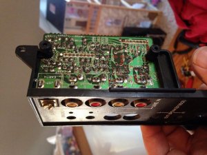
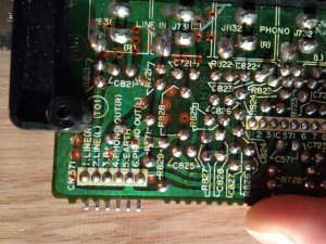
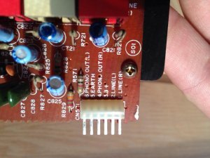
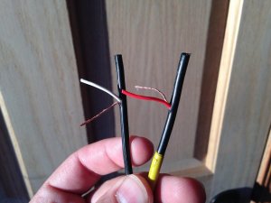
Cut the RCA ends off your BT module. Red is (+) 'right' and White is (+) 'left'. The bare copper shown is neutral (-) shared between the 2 signals at the PCB. Those will be twisted together and soldered to the board on the same pad. Another thing to remember is that the center pin of a RCA plug is positive (+), the outer ring is of the plug is negative (-) or 'common'.
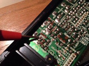
Solder the red (+) 'right' signal wire to the RCA jack pad shown below.
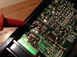
Solder the white (+) 'left' signal wire to the RCA jack pad shown below.
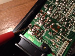
For the shared (-) line I twisted the two together and soldered another black wire whip to those for some slack and because the wires twisted together were really chunky and too big to make a clean connection to the PCB. So the black wire is the shared (-) and is soldered to a shared ground/common/(-) pad as shown below.
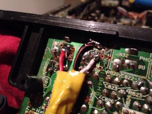
I was having the problem getting my BT signal to get into the line-in circuit. These RCA jacks are kind of like a 'switched' type where you have to have a physical rca plug pushed into the jack for the input to work. When a rca plug is not in the jack, I noticed the common (-) and positive (+) legs touch in the back of the jack when nothing is inserted. Norm told me that this is because it is designed to short (+) to ground to prevent/reduce noise from getting into the system.
My solution was to just bend the ground tab away from the positive tab so it won't short anymore. It was the easiest solution I could figure at the time, but I don't know if long term is going to be OK.
Notice the back side of the red and white jack. There is a tab that hovers across the middle that is (-) and is stationary. The tab that comes up from the bottom is the (+) and is sprung UP to touch the (-) tab when nothing is inserted.
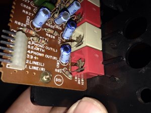
I took the (-) tab and bent it away so it doesn't touch anymore on the red and white jack.
Red jack tab bent, white jack tab not bent (both red and white jack tabs will need to be bent out of the way):
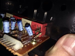
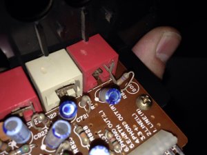
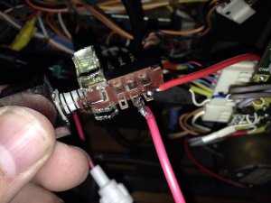
Red wire to the far right is 12v (+) BEFORE the switch. When switch is depressed it then will send 12v (+) through the switch and into the red wire that is attached to the center pin of the switch. This turns the BT module on/off with a simple push of the button so it isn't always on.
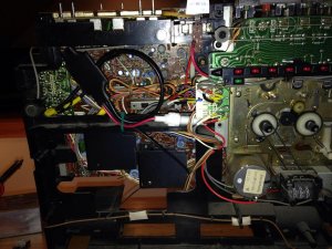
This is an overall picture with the BT module routed in the chassis.
Right now I am finished tapping the line-in pads on the PCB.
I tried using 12v at the cassette motor but as soon as I plug in the boombox I get this horrid buzzing noise and I unplugged it right away and desoldered my power/ground connections.
Here are a few side panel pictures so you can see how nice everything is labeled on the board. Sorry for the sideways pics. You can see directly under the line-in jacks the solder pads for (+) left and right as well as the shared (-) pads and traces.


Cut the RCA ends off your BT module. Red is (+) 'right' and White is (+) 'left'. The bare copper shown is neutral (-) shared between the 2 signals at the PCB. Those will be twisted together and soldered to the board on the same pad. Another thing to remember is that the center pin of a RCA plug is positive (+), the outer ring is of the plug is negative (-) or 'common'.

Solder the red (+) 'right' signal wire to the RCA jack pad shown below.

Solder the white (+) 'left' signal wire to the RCA jack pad shown below.

For the shared (-) line I twisted the two together and soldered another black wire whip to those for some slack and because the wires twisted together were really chunky and too big to make a clean connection to the PCB. So the black wire is the shared (-) and is soldered to a shared ground/common/(-) pad as shown below.


I was having the problem getting my BT signal to get into the line-in circuit. These RCA jacks are kind of like a 'switched' type where you have to have a physical rca plug pushed into the jack for the input to work. When a rca plug is not in the jack, I noticed the common (-) and positive (+) legs touch in the back of the jack when nothing is inserted. Norm told me that this is because it is designed to short (+) to ground to prevent/reduce noise from getting into the system.
My solution was to just bend the ground tab away from the positive tab so it won't short anymore. It was the easiest solution I could figure at the time, but I don't know if long term is going to be OK.
Notice the back side of the red and white jack. There is a tab that hovers across the middle that is (-) and is stationary. The tab that comes up from the bottom is the (+) and is sprung UP to touch the (-) tab when nothing is inserted.

I took the (-) tab and bent it away so it doesn't touch anymore on the red and white jack.
Red jack tab bent, white jack tab not bent (both red and white jack tabs will need to be bent out of the way):


Red wire to the far right is 12v (+) BEFORE the switch. When switch is depressed it then will send 12v (+) through the switch and into the red wire that is attached to the center pin of the switch. This turns the BT module on/off with a simple push of the button so it isn't always on.

This is an overall picture with the BT module routed in the chassis.

Hahahaha. Joe, it's an extremely common mistake. EVERYONE seems to think resistors cut voltage. Resistors cut CURRENT, not voltage.blu_fuz said:#1 problem holding me up is the power source. I'm just going to have to make a 12v regulated power for the BT module..... Only problem is I DON'T KNOW HOW, I'm stuck. This should be way easier to get a 12v signal in this radio. I ran 2 1k resistors in series and it would not drop the 20v power down at all, what is going on with that?! I thought it would be as simple as getting some resistors in there and I was wrong.
In your case, the current draw of a meter is so low, to the extent that it will have virtually NO EFFECT on the source voltage supply because it's almost as if no current is flowing. I'm a bit busy right now but #1, can you put your blutooth device in series with your meter using the amps measuring mode and then find out how much current your blue tooth device consumes while operating. Don't just turn it on, actually play some music through it. If the current draw is low enough, then you might be able to "sneak" some juice through one of the M70's internal regulators. And no, the cassette motor is not regulated as far as I know. If not, then I can send you a 12v regulator chip and you can use it to build your supply. It's not that hard. Or depending upon how much current is needed, we can even use a simple zener diode, resistor and NPN transistor to build one.
jimmyjimmy19702010
Member (SA)
Why not use one of these little things? - you run power to the module, hook up your volt meter to the other end and adjust the pot until you get 12 volts. They are a pretty small module so you should have room somewhere inside an M70.
Under $4 shipped.
http://pages.ebay.com/link/?nav=item.view&alt=web&id=131388173416
James....
Under $4 shipped.
http://pages.ebay.com/link/?nav=item.view&alt=web&id=131388173416
James....

That's an easy solution. But again, if current consumption of his module is low enough, just sneak some from the onboard regulator is easiest.
jimmyjimmy19702010 said:Why not use one of these little things? - you run power to the module, hook up your volt meter to the other end and adjust the pot until you get 12 volts. They are a pretty small module so you should have room somewhere inside an M70.
Under $4 shipped.
http://pages.ebay.com/link/?nav=item.view&alt=web&id=131388173416
James....
jimmyjimmy19702010
Member (SA)
Sorry Norm, I wasn't responding to your response as it was posted while I was finding the Ebay link.Superduper said:That's an easy solution. But again, if current consumption of his module is low enough, just sneak some from the onboard regulator is easiest.
I know that Jimmy and Joe may have to go that route, of adding a regulator. That one is cheap and simple and will work. But if he can tap off the system, then he won't need to juggle another module and try to find room for it, etc.
Updated my pictures with wordzzzzz.
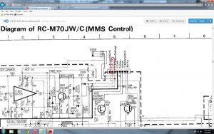
I'm going to get out my circuit diagram and see if they have a 12v marked so I have a starting point for power. The goal is to install this BT module without a pile of other parts needed to make it work. Trying to go the simplest route and also the safest because I don't want you guys damaging your M70 because of a mistake I made.
I'm going to get out my circuit diagram and see if they have a 12v marked so I have a starting point for power. The goal is to install this BT module without a pile of other parts needed to make it work. Trying to go the simplest route and also the safest because I don't want you guys damaging your M70 because of a mistake I made.
Superduper said:can you put your blutooth device in series with your meter using the amps measuring mode and then find out how much current your blue tooth device consumes while operating. Don't just turn it on, actually play some music through it. If the current draw is low enough, then you might be able to "sneak" some juice through one of the M70's internal regulators. And no, the cassette motor is not regulated as far as I know. If not, then I can send you a 12v regulator chip and you can use it to build your supply. It's not that hard. Or depending upon how much current is needed, we can even use a simple zener diode, resistor and NPN transistor to build one.
I will check the current tonight and report back.
The cassette motor is strange.... when the boombox is OFF and the motor is not running I am getting 20v at the motor. I thought that was strange. When the boombox is ON, even if the motor is still not running, one of the motor pads drops to 12v. I tapped my (+) there to feed the BT module, keeping in mind to make sure the BT switch was OFF so I didn't accidently feed 20v into the module. I just wanted to do some testing but as soon as I plugged in the boombox is when I got the nasty buzzing noise in the speakers, so I took the power feed off the motor.
^ That is a great option and pretty dang cheap too. Thanks. Hopefully I don't have to go that route, but who knows anything is possible!jimmyjimmy19702010 said:Why not use one of these little things? - you run power to the module, hook up your volt meter to the other end and adjust the pot until you get 12 volts. They are a pretty small module so you should have room somewhere inside an M70.
Under $4 shipped.
http://pages.ebay.com/link/?nav=item.view&alt=web&id=131388173416
James....
Joe, I believe that rail is powered by X505 (2SD439). Check and verify but if it is, it's a pretty robust device so you should be fine (I'm only guessing since you didn't provide current consumption data of your bluetooth: you need to measure to be sure). You might want to avoid using the cassette deck simultaneously if you do use that rail, as the autostop feature relies on that rail as it powers the autostop solenoid. As you know, those solenoids can consume a lot of curent. But chances are that you'll be fine and if it blows, you can rebuild that regulator rather easily.
Lasonic TRC-920
Moderator
Hard to believe it would draw that little but that's great. Go for it bro. That X505 regulator rail should handle it with no issues.


