JVC RC-727L radio board

mariuseek

New Member
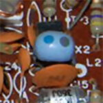
I identified the inductor I need. The part number from the service manual is 03226-1K, named "FM IF Trap". Is from the other JVC model, but has the same manual part number.
It is marked with a blue dot and one that looks more like purple, which according to the color code means it has 67 μH. Can I replace it with other 67 μH inductor even if it has a different build? I don't know how important this component is.
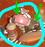
On my board the original one has been replaced with a smaller size inductor in parallel with something pink that looks like a ceramic capacitor, see the picture.
 

Attachments

  • inductor ok.jpg
    inductor ok.jpg
    131.3 KB · Views: 11
  • old.jpg
    old.jpg
    132.7 KB · Views: 9

Superduper

Moderator
Staff member
I think the 2nd color is grey, and on the side of the inductor after the grey dot, there is a silver dot meaning it's (10)-2 power or divided by 100. Meaning it should be 0.68μH. Just my guess. I didn't confirm what you said, but if you are saying that this is an FM IF trap, it would seem that it's purpose is to filter out FM signals from entering active components such as preamps. This would typically be just before the tuner output where only audio signals are desired (and no RF is desired in the signal at that point). Based on this, I am presuming it would have zero effect on the tuner's receiving bandwidth.
 

mariuseek

New Member
Job done. The 87.5 to 108 MHz band has been successfully restored. It was my first radio attempt to fix, so I'm glad I succeeded.
I rebuild and changed the 2 copper coils plus the FM IF trap inductor. The coil one on the tube was missing the ferrite core, so I cut a screw and fitted it there. I wound the FM IF trap inductor on the basis of an old one. I made it about 60 μH, I didn't have anything to measure it with high precision, but seems like it works well.
All afternoon I was fiddling with the board. It seems crazy, but I didn't use any measuring device, everything was adjusted by ear and comparing to another radio. Now is working and sounds very good. It may not be 100% correct as by the book, but for me it is what is needed. The stations appear on the scale where they should, have a good signal and can be heard very well.
I have attached pictures of what was before and how it is at the end. I will pour wax over the FM oscillator coil to fix it in place.
Thank you all for your support.
 

Attachments

  • before.jpg
    before.jpg
    337.8 KB · Views: 7
  • after.jpg
    after.jpg
    275.4 KB · Views: 7
  • Like
Reactions: floyd

Superduper

Moderator
Staff member
It wasn't clear from the orig images that the ferrite core in L4 was missing but that is essential in adjusting the FM bandwidth. Without that slug, the value would have been way off. I suspect that it was likely the main reason your tuner bandwidth was off and the other loop coils probably could have been left alone. Those slinky coils are adjusted by simply expanding and compressing them. It's just a coil of wire, not much to them and they simply don't go bad with the miniscule current they carry. Did you rewind L6 and tapped it in the middle? Also, when you say you wound the IF trap inductor to 60uH, are you speaking of L5? Because here are closeups of PN# 03226-1K.
IMG_9787.jpg

IMG_9786.jpg

Inductors and Resistors can't be properly identified with 2 colors. There's always at least 3 bands, preferrably 4 or more. It's not possible to only recognize just 2 colors because then there will be no suffix multiplier. With only 2 colors and no multiplier, then there's no way to recognize any value more than 99, or less than 1. Your photo was straight on, and blurry. These are closeups of the same part. If you take the silver into consideration, then you will need to divide the 2 digit number by 100 to get the true value. A 4th band, if present would identify the tolerance. Ergo, the value should be 0.68uH. 60uH will be 88x higher than the original value. Luckily this is a FM trap and not in the oscillator circuit which would probably break FM entirely. Will it work as designed with such a value discrepency? Probably not as intended and maybe there will be some FM RF leaking into the audio circuits, but as you say, if it's good enough for you, then it's good enough.
 

mariuseek

New Member
Coils L4 and L6 work well. Adding the core to the L4 made a huge difference. L6 was strangely made of joints and I remade it with 3 windings like the original one. Yes, at L6 I connected the tap and expanded it a little until it started working. As for L5, not having a clear picture at that time, I maked it 68 uH too see if it works. Now that I have the information, I will try to rewind it to the correct value. I always try to do things right.
Thanks for your support.
 
Last edited: