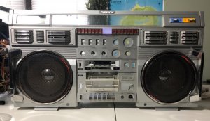
"Desperate Dad's" Conion C-100F Restoration

Status
Not open for further replies.

Bloodhound

Member (SA)
Thank you for the positive feedback! We got started yesterday and so far we're doing ok.

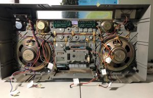
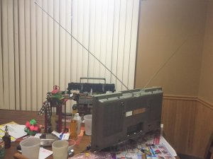
Got the rear cover removed and thoroughly cleaned. We also cleaned up the power supply. There appears to be rust staining on the power supply here and there so I'm going to try a touch of clr to see if that will clean it up.

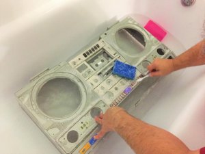
The worst has been the cleanup. Goggles and respirators are a must here with the mouse droppings etc. We've got about 50% of it cleaned up. Once we get the chassis removed we should be able to make quick work of cleaning the front case. Thanks to other resto posts we plan on giving it a scrub down in the bathtub as that makes the most sense.

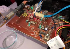
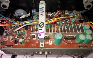
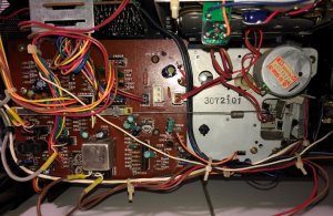
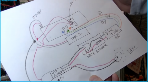
We've got several pictures, notes and diagrams already and every connection is being tagged with the connection and PCB board numbers.

I must say that you folks are an ambitious and talented bunch. Some of the things you do in these resto threads are unbelievably impressive not to mention the reproduction of key parts!

The only let down for us at this point is my son's desire to do a few mods that I am NOT prepared for. I'm old school and like keeping things original. He wants to do a hard install on the bluetooth internally and add a power toggle switch to the rear of the case. He also wants to add LED's.

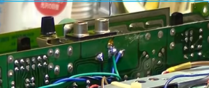
I have only a novice knowledge in electricity and ZERO knowledge of electronics. I'm giving myself a crash course with a few youtube tutorials but these things take time. I'm sure I can tie into the RCA jacks internally but I'm lost when it comes to tapping into the power supply.

I'm hoping to get as far as adding the bluetooth like he wants. Then I'll tackle the LED's in the future when I'm comfortable and know what in the hell I'm doing! LOL.

Pics coming soon and thanks again for helping us! :)
 

Bloodhound

Member (SA)
blu_fuz said:
Good for you guys and I love that he is as stoked about it as you are!
I know right? LOL... I think I'm just happy to have an excuse to spend more time with him. Gonna milk it for all its worth! :)

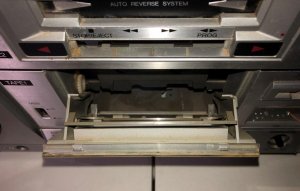
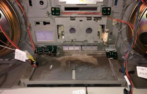
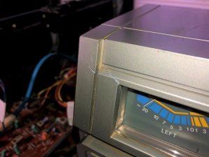
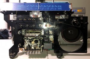
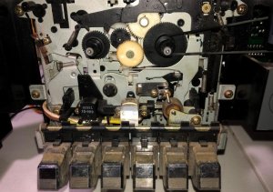
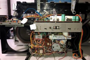
We ran into our first problem yesterday. After a bit of a struggle we were able to remove the chassis from the front case. The tape head mechanism is locked in the up position. It was hitting up against the plastic case edge and appears to be stuck. I tried spinning the flywheel by hand and it it just freewheeled. The belt is melted and all that got me was black fingertips! I managed to push it down by hand just enough to allow the case to slide over it and out while depressing the stop button. I'm hoping I didn't damage anything. The whole of the tape one mechanism is locked up. If there was any lubricant it has no doubt turned to cement. On a good note though the tape door opens and closes smoothly and their doesn't appear to be any damage to the door or springs. Works great in fact! :)

For now we're going to focus on stripping down the front case for repair and repaint. Then we'll focus on the chassis.

1.JPG

1b.JPG

2.JPG

3.JPG

4.JPG

5.JPG

6.JPG

7.JPG

8.JPG

9.JPG

10.JPG
 

floyd

Boomus Fidelis
Once you get the new belts on spin the deck by hand a few times just to make sure everything is moving like its supposed to . these have an interlock on the deck that prevent the door from opening if the tape heads are in the play position.

I've had to force these deck doors open before , I just shake the inner chassis until it frees up .
 

Transistorized

Member (SA)
This is really a great thing. So nice to see that there are younger folks interested in these things as well. A fantastic eye your son has. He picked the icon of the era for sure. A brave task for your first box restore. I feel confident that you guys will prevail in your endeavor to get this going 100% and looking great.

:popcorn:
 

caution

Member (SA)
Two questions for anyone in the know, to help with his Bluetooth install.

Question 1: While I was looking into a good spot to patch the Bluetooth audio into, I noticed that the aux/phono switch swaps out the inputs and outputs of the phono amp with a 39k/6.8k voltage divider for aux mode. I'm assuming the Bluetooth module's outputs have either a series resistor or voltage divider as well, but does that matter? Does having two sets of resistors on the audio path affect things in a non-trivial way? You never want to bypass The C100's aux resistors, right?

The red dots would be like plugging something into the back for aux mode, but doesn't disturb phono. Tying to the purple dots does that too, but also bypasses R110 and R111, with R112 and R113 still pulling to ground (updated image with more info)

49162141868_8ff77b0994_h.jpg

49147910933_d2d808a13c.jpg


Question 2: Providing power to the Bluetooth module would be a piece of cake if one only wanted to use it on AC, you could simply install the Bluetooth's wall wart inside the box and be done with it. But trying to attach it to switched power, which is 15-18V, would need some sort of voltage regulator/DC-DC converter to get down to 5V, but does an off-the-shelf solution exist, or would it be best to engineer something out of individual components (5V regulator, heat sink, caps, etc.)
 

Bloodhound

Member (SA)
Reli said:
Here's the best glue for case cracks. It actually melts the plastic together ;-)
https://www.amazon.com/SCIGRIP-Adhesive-Applicator-Bottle-Needle/dp/B079J4CNJ4/
Thanks for the tip Reli! Appreciate that! :)

JVC Floyd said:
Once you get the new belts on spin the deck by hand a few times just to make sure everything is moving like its supposed to . these have an interlock on the deck that prevent the door from opening if the tape heads are in the play position.

I've had to force these deck doors open before , I just shake the inner chassis until it frees up .
Thanks JVC Floyd. Once the new belts are installed will spinning the flywheel release the tape head from the upward play position? Not sure how else to accomplish that.

Transistorized said:
This is really a great thing. So nice to see that there are younger folks interested in these things as well. A fantastic eye your son has. He picked the icon of the era for sure. A brave task for your first box restore. I feel confident that you guys will prevail in your endeavor to get this going 100% and looking great.

:popcorn:
Thanks for the kind word Transistorized! I think the key here is exposing kids to such things. He showed a few friends some pictures and they've asked to come see it and check it out. Appreciate the vote of confidence as well. With the help we're getting here on the forum we should be AOK! :)

caution said:
Two questions for anyone in the know, to help with his Bluetooth install.

Question 1: While I was looking into a good spot to patch the Bluetooth audio into, I noticed that the aux/phono switch swaps out the inputs and outputs of the phono amp with a 39k/6.8k voltage divider for aux mode. I'm assuming the Bluetooth module's outputs have either a series resistor or voltage divider as well, but does that matter? Does having two sets of resistors on the audio path affect things in a non-trivial way? You never want to bypass The C100's aux resistors, right?

The red dots would be like plugging something into the back for aux mode, but doesn't disturb phono. Tying to the purple dots does that too, but also bypasses R110 and R111, with R112 and R113 still pulling to ground.

49147943503_45a3009f80_h.jpg

49147910933_d2d808a13c.jpg


Question 2: Providing power to the Bluetooth module would be a piece of cake if one only wanted to use it on AC, you could simply install the Bluetooth's wall wart inside the box and be done with it. But trying to attach it to switched power, which is 15-18V, would need some sort of voltage regulator/DC-DC converter to get down to 5V, but does an off-the-shelf solution exist, or would it be best to engineer something out of individual components (5V regulator, heat sink, caps, etc.)
I don't know if this helps Eric but I noticed in Teddy Hashee's Clairtone 7980 video at (33:10) he ties into the 15V-18V power supply for tape deck 2 at CN207. Somehow he uses a car charger socket and USB charger rated at 5V. He doesn't appear to have anything in between to step down the voltage. He also wires up to the RCA inputs at a different location on the board. I don't know if the Clairtone is different from the Conion so not sure if this is helpful or not. He does add his own ground loop noise eliminator into the mix as well which is something I was hoping to avoid.

https://www.youtube.com/watch?v=L8hc9cK21Rs

Bluetooth Mod.png

RCA.png
 

caution

Member (SA)
Oh my god I totally spaced the car adapter. They're made to take 14+ volts, good to go!
With any luck it sounds clean straight away.
 

Bloodhound

Member (SA)
caution said:
Oh my god I totally spaced the car adapter. They're made to take 14+ volts, good to go!
With any luck it sounds clean straight away.
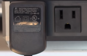
I've noticed that our Bluetooth units power supply is rated at with 5V DC 150ma output..

Untitled.png

Most of the dual USB charging adapters I can find online are rated at 5V but have much higher amperage ranges. I'm seeing 1.5amps and up. Won't that pose a problem? Again, electronics was like "magic" to me just a few days ago so if this is a stupid question I apologize!
 

Transistorized

Member (SA)
Bloodhound said:
Oh my god I totally spaced the car adapter. They're made to take 14+ volts, good to go!
With any luck it sounds clean straight away.

Most of the dual USB charging adapters I can find online are rated at 5V but have much higher amperage ranges. I'm seeing 1.5amps and up. Won't that pose a problem? Again, electronics was like "magic" to me just a few days ago so if this is a stupid question I apologize!
With amperage, the device will only pull what it needs. Now if you went higher in voltage that would cause issues.
 

caution

Member (SA)
Bloodhound said:
Most of the dual USB charging adapters I can find online are rated at 5V but have much higher amperage ranges. I'm seeing 1.5amps and up. Won't that pose a problem?
Nope! A circuit only draws as much current as it needs, based on its load. That value is more of a max rating, you can only power circuits that demand up to that much current.
 

Superduper

Moderator
Staff member
caution said:
Two questions for anyone in the know, to help with his Bluetooth install.

Question 1: While I was looking into a good spot to patch the Bluetooth audio into, I noticed that the aux/phono switch swaps out the inputs and outputs of the phono amp with a 39k/6.8k voltage divider for aux mode. I'm assuming the Bluetooth module's outputs have either a series resistor or voltage divider as well, but does that matter? Does having two sets of resistors on the audio path affect things in a non-trivial way? You never want to bypass The C100's aux resistors, right?

The red dots would be like plugging something into the back for aux mode, but doesn't disturb phono. Tying to the purple dots does that too, but also bypasses R110 and R111, with R112 and R113 still pulling to ground (updated image with more info)

Question 2: Providing power to the Bluetooth module would be a piece of cake if one only wanted to use it on AC, you could simply install the Bluetooth's wall wart inside the box and be done with it. But trying to attach it to switched power, which is 15-18V, would need some sort of voltage regulator/DC-DC converter to get down to 5V, but does an off-the-shelf solution exist, or would it be best to engineer something out of individual components (5V regulator, heat sink, caps, etc.)
Re Question 1: Those resistors are very important because they determine the input impedance that the output source device will see. Obviously, a device which is designed to drive some form of speaker system will expect relatively low impedance but anything that is outputting a line-type of signal will expect to see high impedance of at least 10k Ω or more. You might want to convert that resistor to a lower amount (10k Ω?) but the question is why would you? Most of these consumer DIY type of modules come with very limited specifications so there's nothing to suggest that 39k is too high, and even if it was that is not the only thing to consider, you also have to consider the boombox itself. Some engineer someplace designed that voltage divider system considering not only the input impedance that the source device will see, but also the amount of voltage/current that the next amplification stage will see, and I'm sure they carefully calculated the values of the resistors required for the transistors in the next amplification stage to operate in the middle of its linear active region. Any changes to one factor will require readjustment in others to compensate for the change to arrive at the same result, the subject of which I'm not even going to begin to try to interpret what that was. Simple answer is inject the signal as if it were being injected through the RCAs with all the orig circuitry intact.

Re Question 2: Modern wall warts today are all digital switching PS types. They require a ton of components and much higher investment in design costs to develop compared to analog power supplies, but because the parts in an analog supply, especially the transformer are far more inexpensive, the design costs of a digital supply are easy to fold into and become a miniscule figure when mass produced. However, the downside is that they emit interference that can affect legacy electronics that were not designed to properly shield such interference. Not saying that it will, but it might be a problem. I once calculated the load that one of these bluetooth receivers consume and it's not much. A simple modern voltage regulator IC is plenty robust to supply the needs of the bluetooth device, possibly even without a heatsink, but monitor the heat level with IR temp guage first in operation to confirm. Otherwise small heatsinks are easy to find and cheap to get. An alternative is to just use a simple zener/transistor regulator circuit as used in countless boomboxes and those won't introduce noise but some testing will need to be conducted to see if it can supply the power needs (I suspect it's no problem) in common form, or whether a more complicated design needs to be developed instead.

One other thing to consider. If an internal bluetooth add-on doesn't have it's own function mode but instead is tethered to the line-in jacks, then that circuit will always be bluetooth circuit enabled. Even if it was turned off, the tethered circuits will always piggy back onto that line unless it was switched to cut off the connection. For example, in a normal circuit design, the electronics tethered to any circuit can be untethered by switching such as function or record-bar or muting transistors, etc. It isn't just left dangling even if unpowered. Look at any boombox schematic and you'll see switches everywhere. It's meant to reduce or eliminate the possibility of the unused circuitry to introduce noise. And since the bluetooth really is just hardwired to the line-in jacks anyway, how about just building the bluetooth receiver into a hobby box with a battery pack and just plug in externally onto the line jacks? Would be a simple weekend project, will not introduce any ground loop noise, and easy to connect/disconnect.
 

Bloodhound

Member (SA)
Thanks for the Amperage lesson Transistorized & Caution! Glad to know it won't be a problem. :)

As much as I'd like to keep the box 100% original I can't do it. It's what my son wants and ultimately his choice. I've found enough off the shelf components to make it happen so I'm confident thanks to everyone's help here we can get it done. I may try and add LED's now as well since I've learned quite a bit in my short time here.

The tear down will continue later today. More pics to come! :)
 

Hajidub

Member (SA)
Almost time to get him hooked on the classics (EPMD, Eric B, Special Ed), and show him where the music originated! Great job so far Bloodhound, you're a great dad!
 

floyd

Boomus Fidelis
I will say this , when I look at the conion this box is everything great about the 80's and the looks are about as intimidating as could be imagined.

I mean its literally the t-800 version of a boombox.
 

Bloodhound

Member (SA)
Hajidub said:
Almost time to get him hooked on the classics (EPMD, Eric B, Special Ed), and show him where the music originated! Great job so far Bloodhound, you're a great dad!
Thank you Hajidub! Totally agree! I played "Looking For The Perfect Beat" by Africa Bambataa on it prior to starting the tear down and he totally digs it! :)

JVC Floyd said:
I will say this , when I look at the conion this box is everything great about the 80's and the looks are about as intimidating as could be imagined.

I mean its literally the t-800 version of a boombox.
Totally agree! It's definitely grown on me.

I don't have any super interesting pics but will share some soon. We spent 14 hours working on it this weekend and we've made tons of progress. We got into "the zone" and realized we didn't take many pics. We managed to remove the boards with the switches and sprayed Deoxit into all and worked them to the max!

Next up came the tape decks. We removed both and spent at least 4-5 hours cleaning out seeds, dust, dirt etc. The worst was cleaning the melted remnants of the thick drivewheel belt on deck 1. What a bastard that was. We found pieces of it everywhere. I think we used half a box of Q-tips LOL!!! Was worth the effort though.

We used some folded 2000 grit sandpaper to lightly deburnish all the plastic belt grooves and cleaned everything a 2nd time for good measure. After installing the new belts we carefully turned the drive belt and just like you guys said the tape head assembly snapped out of the play position.

Tape Deck 2 concerns me a bit. The FF and RW buttons dont stay depressed with a cassette inserted. I haven't been able to figure out why. I also don't see a motor speed screw on the back of the motor like Tape 1 has. Can anyone enlighten me as to how deck 2 functions and where to find the motor speed adjustment?

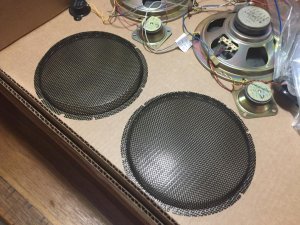
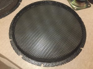
Lastly, the speaker grilles have been glass beaded and they are out for powder coating now. Our plan is to just stay consistent until she's complete again. This has been a very fun and enjoyable endeavor. :)
 

Bloodhound

Member (SA)
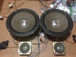
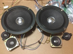
Making progress on the Boombox with my son little by little. Speakers have been cleaned and re-blacked, new antenna's installed and the main case got a bath. Just got the speaker grille's back from Powder Coating and they turned out absolutely perfect!

1.JPG

2.JPG

3.JPG

4.JPG

5.JPG

6.JPG
 
Status
Not open for further replies.