It fired up again and seems to be working fine although now that the decks are working again I've found some issues there. You're right Joe this thing is a mess wirewise but actually the tradeoff is that all the electronics are spread far and wide, making it a breeze to work on!
Conion C100 resto
- Thread starter caution
- Start date
You are using an out of date browser. It may not display this or other websites correctly.
You should upgrade or use an alternative browser.
You should upgrade or use an alternative browser.
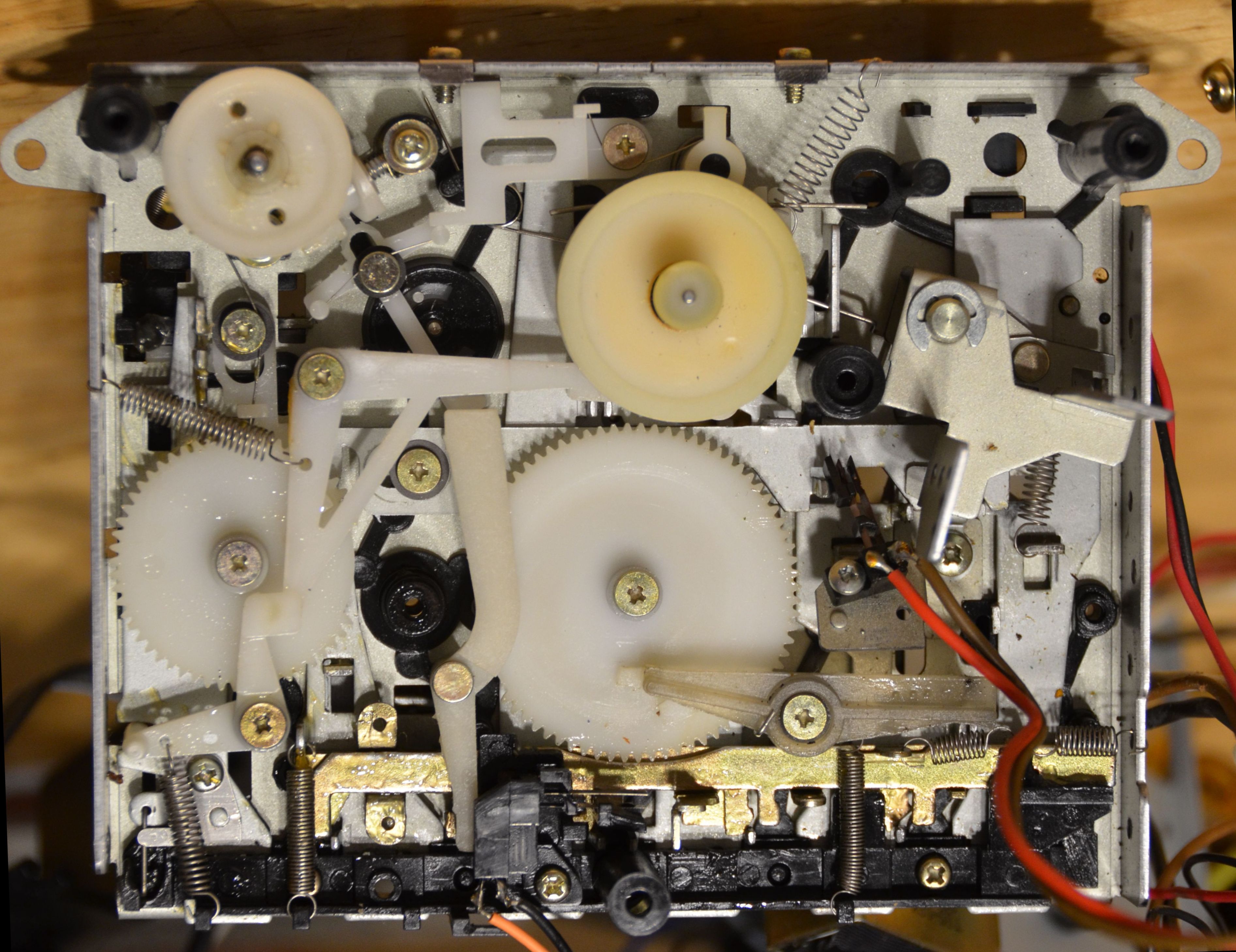
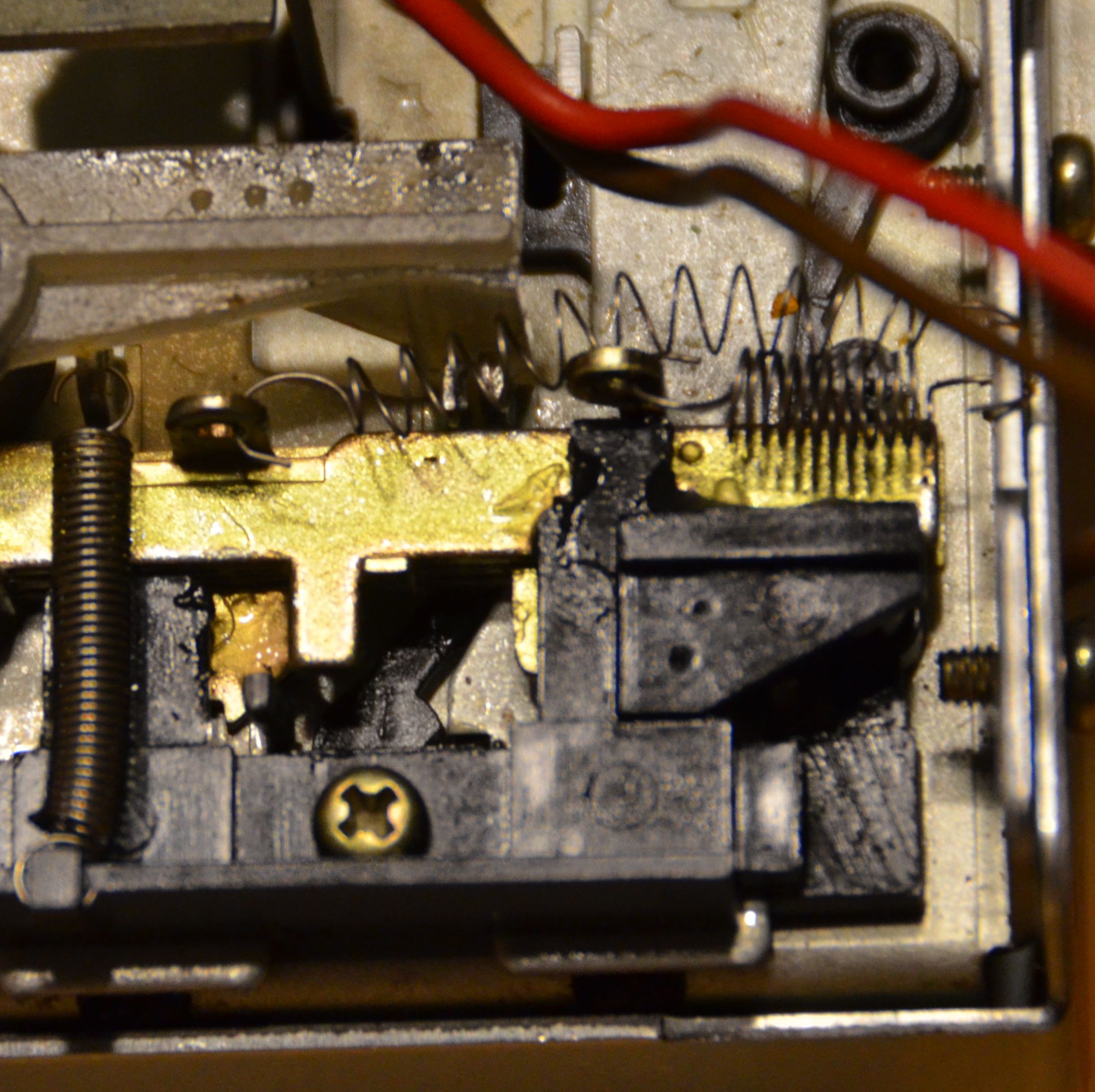
After gettings back together (partially) from the recap to make sure everything still worked, I moved on to the lower cassette deck's fast-forward and rewind buttons, which were jammed. When you press record, you also move a plate that locks out fast-forward and rewind. The plate wouldn't fully return when pressing stop.
I tried lubricating the hell out of it, but the plate is the top of a stack of four, that all move, and to really get in there and clean it all up would've meant taking the entire mecha apart, so I tried to find a less risky solution. The return spring is the inner one of those two short springs in the very lower-right corner. I moved the tie point to be the same as his neighbor, so now he's stretched twice as long but gives me some extra pull on the plate, and works great now. It's actually below the other spring now, where there is no interference. The plate that prevents them from locking down during play mode wasn't engaging correctly either, but that works now also.
Both the upper and lower decks have worm gear mechanisms which make a pendulum-like thing swing back and forth about once a second. I am mystified. What are these for?
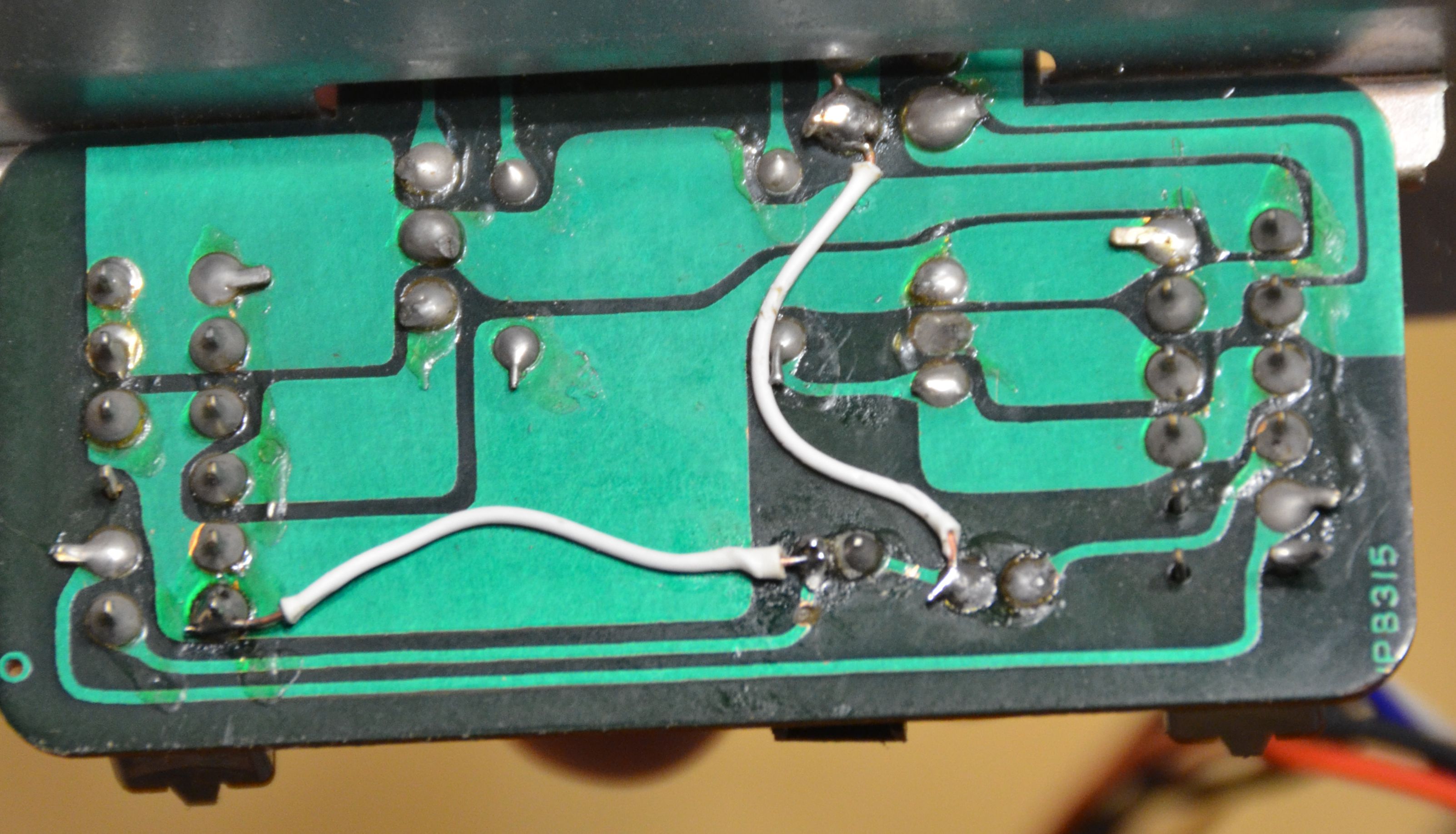
Anyway, after getting that all working again, I got to work on replacing the bulb on the dial light board, which is powered by about seven volts AC, which wasn't enough and flickered too much, so I rewired the power switch board so the dial light connector is the same as the main power LED. The green and yellow wires from the transformer board are actually the output of a second secondary winding, used only to power the dial bulb. I desoldered it and removed it.
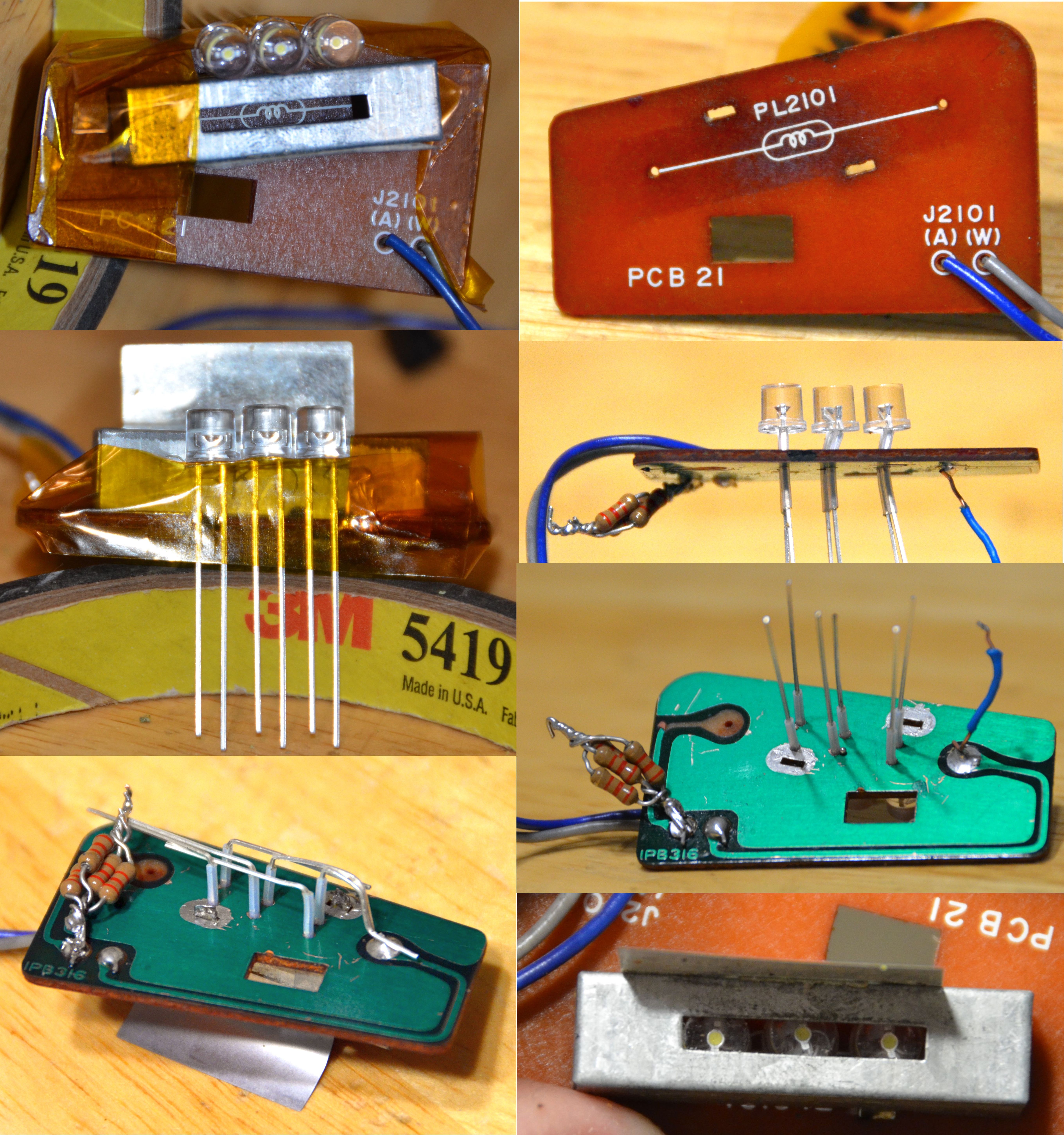
I removed the bulb and the cover for it, and drilled holes for three LEDs. I tried centering them on the bulb symbol printed on the board, but I didn't look closely enough to realize that it's actually centered on the holes for the bulb, not the cover. So, I had to slant the leads for two of them to get them centered on the slot. I put a little bit of spaghetti to protect the leads since the holes go through a big copper flood that the cover's tabs solder to. A couple bends here, a little solder there, and voila! The resistors are running almost too hot to touch, which they weren't doing on the breadboard, so will have to up the wattage some, but the cover doesn't even hardly get warm.
I was going to build a board for the analog VUs like kittmaster did and shine more at the dial from the opposite end as well, but I don't think I need to, which is good because trying to line up those LEDs by placing the frame into the chassis would be messy.
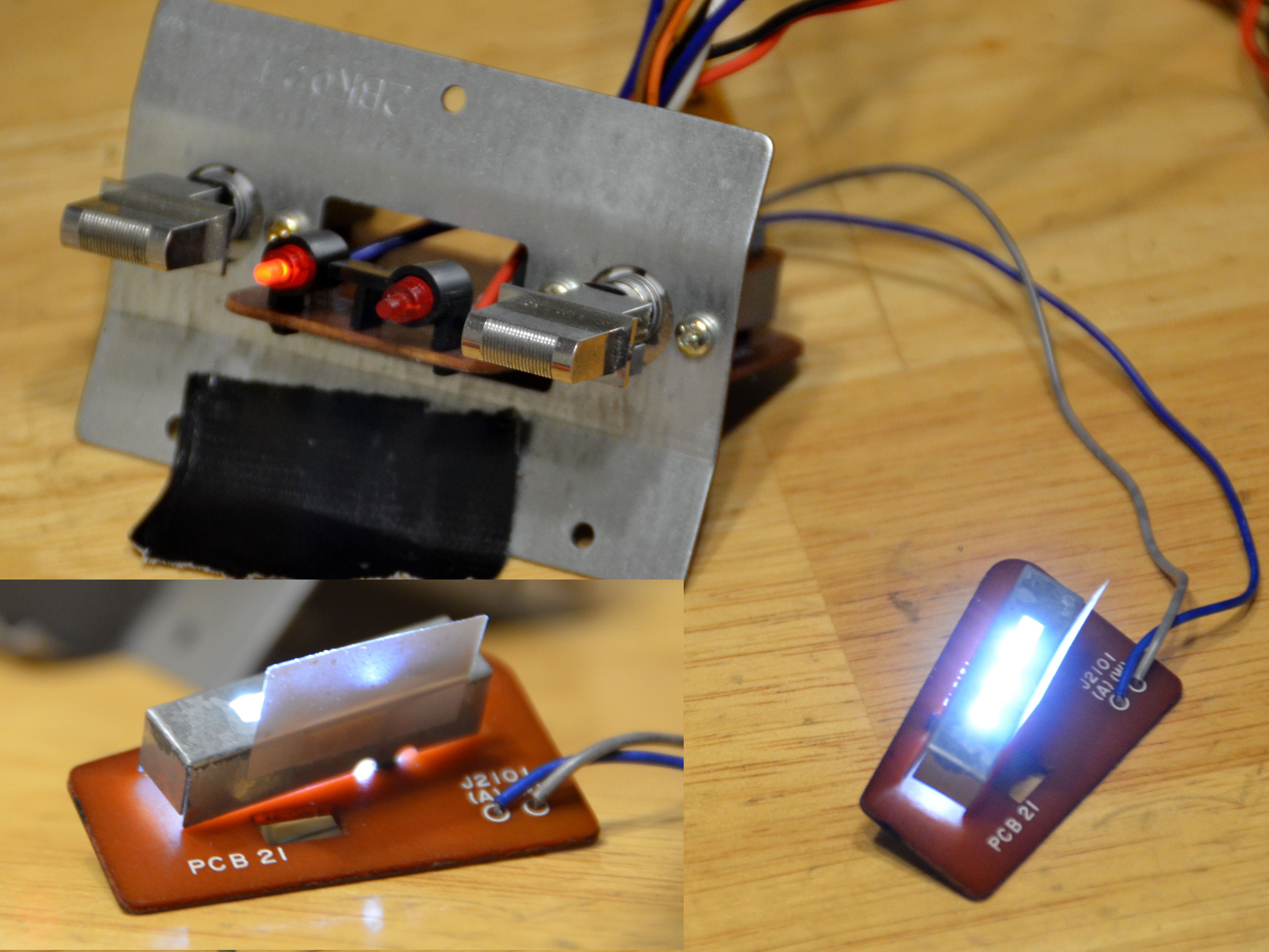


frontside5
Member (SA)
Cpl-Chronic
Member (SA)
Vintage Man
Member (SA)
Thanks guys  Hardmen, that is interesting about the Korean version, maybe they were too cheap to pay for a bulb?? The Japanese version has no switch, the bulb on all the time when it is plugged into an outlet, if you don't plug it in, it will never light up, because the bulb requires the transformer (AC power). It is the only component in the box that uses AC power. Everything else uses DC.
 Hardmen, that is interesting about the Korean version, maybe they were too cheap to pay for a bulb?? The Japanese version has no switch, the bulb on all the time when it is plugged into an outlet, if you don't plug it in, it will never light up, because the bulb requires the transformer (AC power). It is the only component in the box that uses AC power. Everything else uses DC.
JustCruisin
Member (SA)
im_alan_partridge
Member (SA)
You deserve a medal for your massive dedication on this monster.
Well done sir, it looks great so far
Well done sir, it looks great so far

Yep Nichicon Gold! If you go back in this thread, one of my posts has all the recap info complete with direct links to DigiKey for each one. I also priced out the Panasonic FC caps, but I didn't bother posting any of that information because you can't get every value you need with those for the recap, and the cost savings was trivial.
So I got to looking at the piezo tweeters today and surprise, they're both completely dead. I looked around for others who have swapped them out but nada. I'm open to ideas on a solid replacement. Would I need a crossover? How do I make sure it's not too loud or too soft?
So I got to looking at the piezo tweeters today and surprise, they're both completely dead. I looked around for others who have swapped them out but nada. I'm open to ideas on a solid replacement. Would I need a crossover? How do I make sure it's not too loud or too soft?
Man I know! That's okay, it'll be better when I'm done with it 
It finally got warm enough out today to strip the paint off the grilles, and wow. This stuff I bought stripped it right off. Acetone wouldn't even budge it! You can see where I used a wire brush on what I thought was one of only a couple rust spots. Woops.


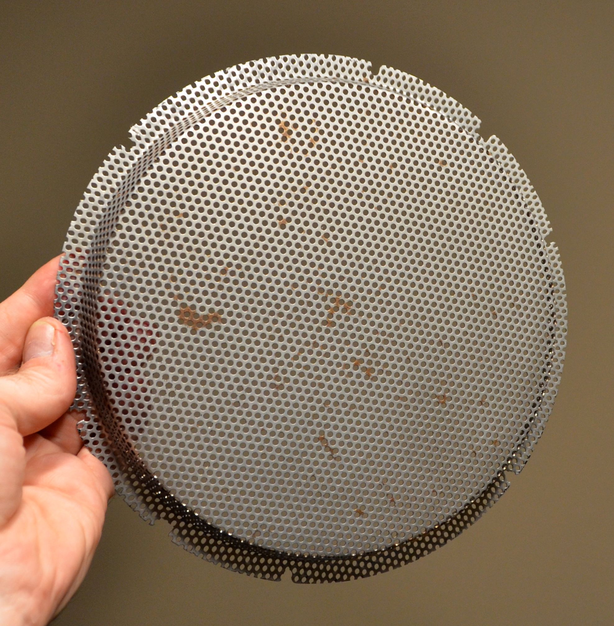


It finally got warm enough out today to strip the paint off the grilles, and wow. This stuff I bought stripped it right off. Acetone wouldn't even budge it! You can see where I used a wire brush on what I thought was one of only a couple rust spots. Woops.


 I gotta tell you, much respect on all the hard work