Custom clock LCD making

thinkchronicity

Member (SA)
Just taken apart the LCD clock that's gone completely black on my Goldstar tsr 581.
Read something about squeezing it would restore much of the display - not a chance, dead as a dodo.
But I see custom made displays are getting affordable now.
Anyone gone down this road? I wonder if you could just send em the old one and they could reverse engineer...(would be handy as i know nothing about lcd spec)
A basic clock display seems quite simple in terms of numbers of segments.
 
  • Like
Reactions: Spax and Brutus442

Superduper

Moderator
Staff member
This is interesting. I doubt you'd find enough people with the TSR581 to get together and produce this project for a clock. But it may not even be that easy because although the manufacture of the LCD might be $100, that does not include the design. Furthermore, it's unclear if the clock LCD display is just an LCD or has an integral clock. It sounds like the guy produced a custom LCD for a lab power supply or something and the controller is on a separate board. Still, this is giving me some ideas but I'm too damn old to care and put these ideas into practice anymore.
 
  • Like
Reactions: thinkchronicity

Superduper

Moderator
Staff member
Ok, I've taken a look at the service manual. Looks like the clock is an integrated clock module, and not an LCD and clock, with a couple of wires that interfaces with the timer control. The best and cheapest method I can think of is to reproduce this using one of those mini controllers, and arduino comes to mind. Although arduino is a little on the large size, postage stamp versions of mini controllers are available. Arduinos can definitely be programmed for a simple clock/timer, and it has plenty of I/O for those 5 input buttons, and to control the timer circuit on the boombox. Oh and there are LCD modules that can plug directly into the arduino too. Now I don't have one of these Goldstars so I don't know the physical size of the original module, but I'm sure with some determined ingenuity, and maybe extension socket for the LCD, it is certainly a doable project.

Screenshot 2025-04-16 at 9.42.37 PM.png
 
  • Like
Reactions: thinkchronicity

thinkchronicity

Member (SA)
Thanks Superduper. You've thrown another curve ball in there to think about! Well, I took the $2 modern clock module apart and extracted the LCD screen. Has all the icons I need and fits the old metal clamping frame LIKE A GLOVE, but the pinout..or rubberout.. is totally different....uses only 18 pads whereas the original has 31 - must be a multiplexer which I can't drive even if I could connect it up somehow. It has a black blob instead of a discrete IC.
Pictured is the 581 clock pcb and the top glass layer of the original LCD. Uses a NEC UPD833 chip, still widely available. The grey wire is positive, the white negative and the yellow is the single control wire, even though the schematic shows two wires going off to the boombox internals.
The plan at the moment is to add some dimensions of the LCD to that pic and find someone to produce a tidy Gerber file that I can tout around some custom LCD makers and get a price. The arduino idea is sounding good though. I hadn't thought of that having no experience with them.
DSCN0673.JPGDSCN0676.JPG
 

Superduper

Moderator
Staff member
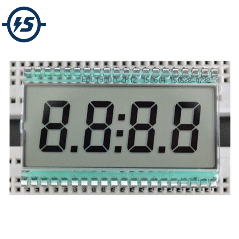
There are tons of videos on youtube showing you how to get started with arduino, etc. and I hardly know anything about them but I did watch enough to understand that you use the arduino as a building block and add from there. There are numerous I/O pins which can be programmed either as inputs or as output controls. As long as you have enough I/O for your project, you are golden. What you would add for a project like this are switches (as shown in the schematic), enough to control the clock functions. You need at least 1 output pin to control the timer function, which for this boombox, I'm not sure exactly what it is controlling..... turning the set on? Turning the set off? Although you can program a clock routine directly into the arduino, it's better to add a RTC (real time clock) module which only costs a couple bucks. This allows the clock to keep time even when the boombox and arduino is powered off and they generally have their own coin battery too. Then you can interface a standard LCD screen. There are numerous sizes but for a simple clock, even the most basic would work. However, a larger one can even display the status of the sleep timer too because there's enough real estate to do more. As for the actual programming routine to be uploaded to the arduino from your computer...... you can either spend lots of time learning to code, or just ask Grok (X) or ChatGPT to write you a routine with the functions you desire, along with the configuration you've decided to build upon. For example, it would need to know what RTC module you have, the type and size of LCD screen (such as 128x8, 64x4, etc.) the run time libraries to be added for those, etc. Then upload it.

As for your existing clock module, the black blob is the actual IC, known as a COB (chip on board). It's actually an IC that is mated directly onto the PCB and then the blob is added to protect it. According to the schematic, there is a + and - going to a 1.5v battery, and although it shows 2 wires going to the boombox timer circuitry, I'm a little puzzled because it appears to shows both wires tied together, which suggests that the clock is powered discretely apart from the boombox, therefore the single control line seems to not be a closed circuit. Depending upon how the timer function works or what it does for the boombox, you can probably still make the arduino do what you want simply by adding a relay circuit (which may require a driver transistor) depending upon the arduino you get and whether it can power the relay directly. I suppose if you ever wanted to learn arduino, why not learn on a project like this?

Microcontrollers have tons of practical applications for restoration of boomboxes. For example, microcontrollers can be programmed to mimic the functions of the notorious deck control IC of the JVC RC-M90 which is now unobtanium. And the M90 is an excellent candidate for a project to make that IC replacement because the service manual is quite comprehensive in describing that IC, the pin-outs, the timing, etc. What an exciting time to be living for young ones. I'm a little too old now to care anymore as I'm probably in a sunsetting stage.
 
  • Like
Reactions: thinkchronicity

thinkchronicity

Member (SA)
Interesting to read as always. I actually have an Arduino that came free with a bunch of bits I bought. I've always felt alienated by the whole thing though - never even hooked it up in several years. Maybe now's the time to see what it's all about.
Yeah the Goldstar clock module is powered discretely by an AA battery.
Well this page is the best I can do for manufacturing info - let's see if they take me seriously. All not to scale of course.DSCN0683.JPG
 

Superduper

Moderator
Staff member
Ok. But what about the pinouts? Don’t you have to know how that lcd will interface with the existing driver and clock controller? Without a pinout being spec’d, would they just randomly assign the pins?
 

thinkchronicity

Member (SA)
Ok. But what about the pinouts? Don’t you have to know how that lcd will interface with the existing driver and clock controller? Without a pinout being spec’d, would they just randomly assign the pins?
If you blow that pic up on a laptop you can hopefully see which pins go to which segments. The interface with the existing i.c. is already worked out, all they have to do is not mess with it.
 

Superduper

Moderator
Staff member
Ah, I see now. Well good luck with this. If you get this worked out, maybe you can help other tsr581 owners out there although frankly, I’d not want to re-use a zebra type connection system if possible because it’s just as likely that the connection failed rather than the actual lcd.
 
  • Like
Reactions: thinkchronicity

thinkchronicity

Member (SA)
Ah, I see now. Well good luck with this. If you get this worked out, maybe you can help other tsr581 owners out there although frankly, I’d not want to re-use a zebra type connection system if possible because it’s just as likely that the connection failed rather than the actual lcd.
Thanks Super. The idea would be to have maybe a hundred made up for others too. Glad you mentioned the anti-zebra sentiment. I WAS going down that route but soldering...should be easy enough - like putting in a large chip. The old LCD failed because it cracked vertically - not due to a blow as the fascia is untouched, but must have been strong sunlight.
 

thinkchronicity

Member (SA)
Off-the-peg news: this one would actually work with a bit of cunning pin joinery to get the "2" on the left hand side to display with only two pins driving from the i.c.
Have a look at the "2" on the original where the segments are deliberately joined up to facilitate this. The rest of the pins are in the same kind of order and the screen size is bang on. Voltage is ok as a 1.5v battery gets effectively doubled by using out of phase square waves to the COM and SEG. Doesn't state the frequency, but i think there's leeway there from 32-100Hz .
You don't really need the original AM/PM icons as it's a 24 hr clock anyway. So only missing the alarm and star symbol. I presume the star symbol indicates SLEEP (switch off) has been set. You could wire up the three extra full stops to indicate the alarm is set i guess. Hmmm....
And from here: https://www.amazon.com/Segment-Display-50-8x30-48x2-8mm-Semitransparent-Positive/dp/B0924TCVHX
 
Last edited: