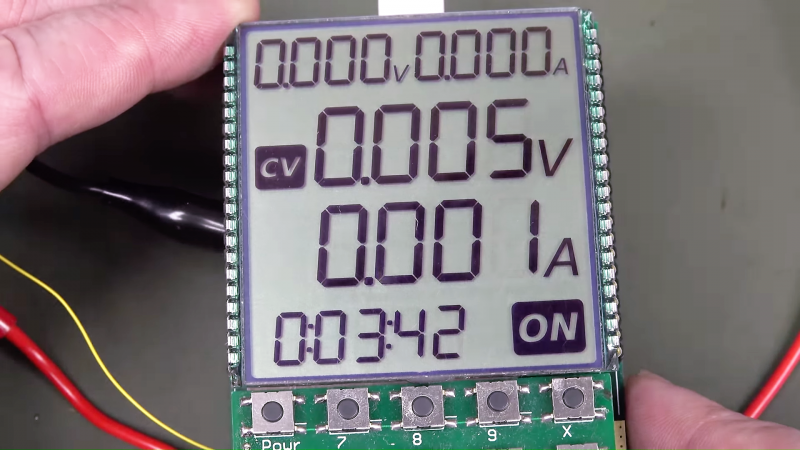
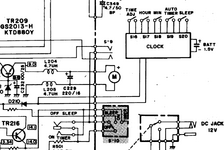
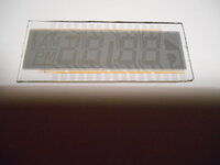
There are tons of videos on youtube showing you how to get started with arduino, etc. and I hardly know anything about them but I did watch enough to understand that you use the arduino as a building block and add from there. There are numerous I/O pins which can be programmed either as inputs or as output controls. As long as you have enough I/O for your project, you are golden. What you would add for a project like this are switches (as shown in the schematic), enough to control the clock functions. You need at least 1 output pin to control the timer function, which for this boombox, I'm not sure exactly what it is controlling..... turning the set on? Turning the set off? Although you can program a clock routine directly into the arduino, it's better to add a RTC (real time clock) module which only costs a couple bucks. This allows the clock to keep time even when the boombox and arduino is powered off and they generally have their own coin battery too. Then you can interface a standard LCD screen. There are numerous sizes but for a simple clock, even the most basic would work. However, a larger one can even display the status of the sleep timer too because there's enough real estate to do more. As for the actual programming routine to be uploaded to the arduino from your computer...... you can either spend lots of time learning to code, or just ask Grok (X) or ChatGPT to write you a routine with the functions you desire, along with the configuration you've decided to build upon. For example, it would need to know what RTC module you have, the type and size of LCD screen (such as 128x8, 64x4, etc.) the run time libraries to be added for those, etc. Then upload it.
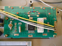
As for your existing clock module, the black blob is the actual IC, known as a COB (chip on board). It's actually an IC that is mated directly onto the PCB and then the blob is added to protect it. According to the schematic, there is a + and - going to a 1.5v battery, and although it shows 2 wires going to the boombox timer circuitry, I'm a little puzzled because it appears to shows both wires tied together, which suggests that the clock is powered discretely apart from the boombox, therefore the single control line seems to not be a closed circuit. Depending upon how the timer function works or what it does for the boombox, you can probably still make the arduino do what you want simply by adding a relay circuit (which may require a driver transistor) depending upon the arduino you get and whether it can power the relay directly. I suppose if you ever wanted to learn arduino, why not learn on a project like this?
Microcontrollers have tons of practical applications for restoration of boomboxes. For example, microcontrollers can be programmed to mimic the functions of the notorious deck control IC of the JVC RC-M90 which is now unobtanium. And the M90 is an excellent candidate for a project to make that IC replacement because the service manual is quite comprehensive in describing that IC, the pin-outs, the timing, etc. What an exciting time to be living for young ones. I'm a little too old now to care anymore as I'm probably in a sunsetting stage.

 hackaday.com
Anyone gone down this road? I wonder if you could just send em the old one and they could reverse engineer...(would be handy as i know nothing about lcd spec)


