Having it follow the system rail makes more sense, I think I'll give that a shot before I tear it apart.
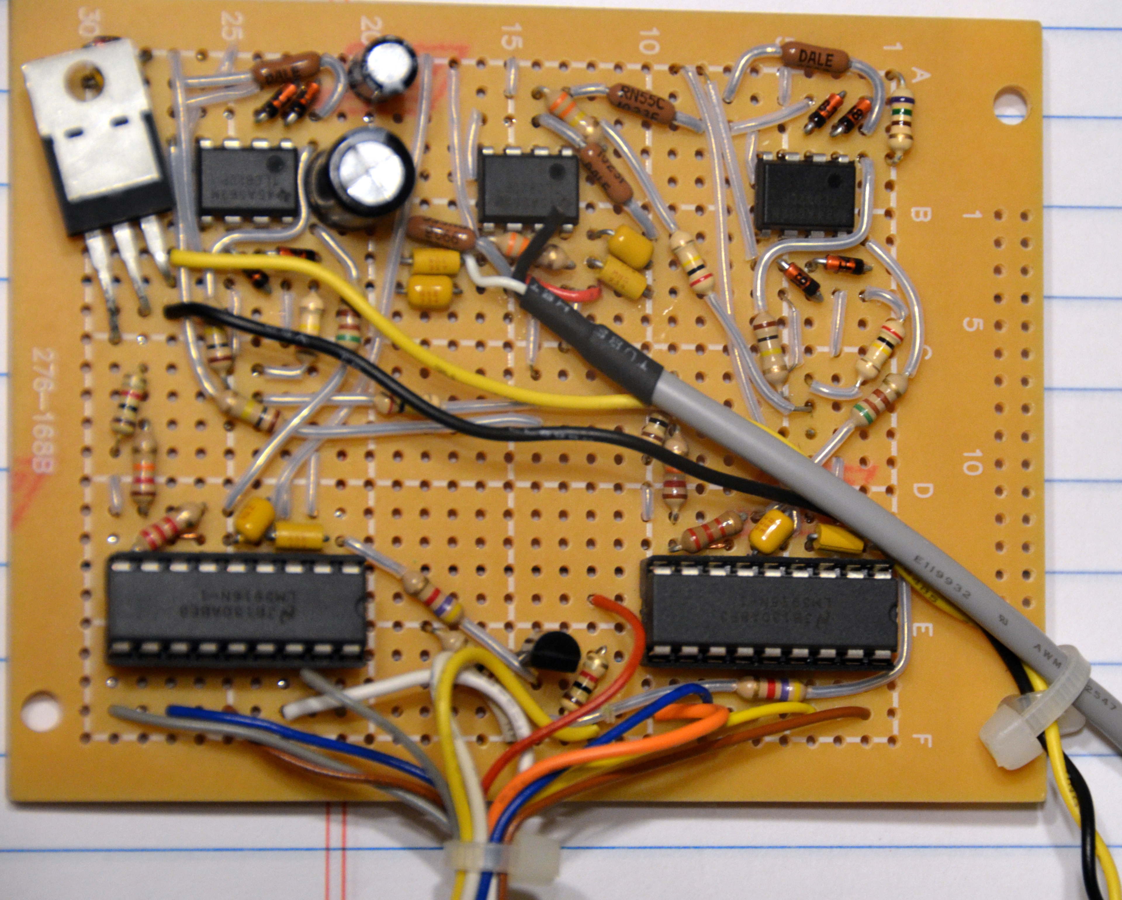
I set up the op amps the same way the guy explained in his project notes, so I guess I was under the impression I was doing what you are supposed to in order to run an op amp in a single rail configuration. So you're saying I'm actually tricking the op amp into a dual supply setup with only rail, and that there is another way to run in true single rail mode? How would that work? It's a full wave detector, so it makes sense to me that it would need a virtual ground in order to see the positive and negative peaks in the signal.
I set up the op amps the same way the guy explained in his project notes, so I guess I was under the impression I was doing what you are supposed to in order to run an op amp in a single rail configuration. So you're saying I'm actually tricking the op amp into a dual supply setup with only rail, and that there is another way to run in true single rail mode? How would that work? It's a full wave detector, so it makes sense to me that it would need a virtual ground in order to see the positive and negative peaks in the signal.
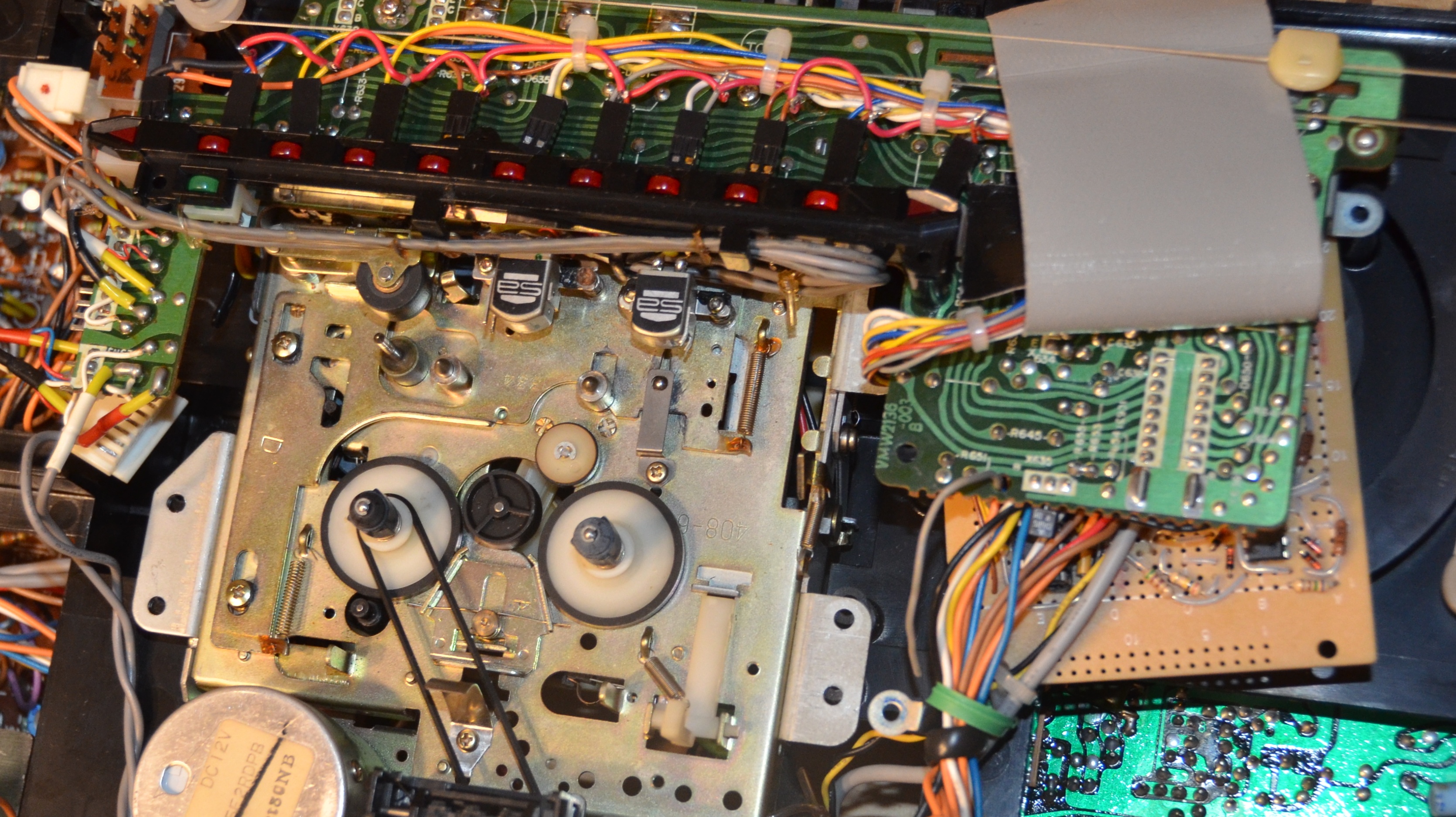
") Looks almost just like a couple of my boxes here when I compare them, so I'm happy.
Looks almost just like a couple of my boxes here when I compare them, so I'm happy.")
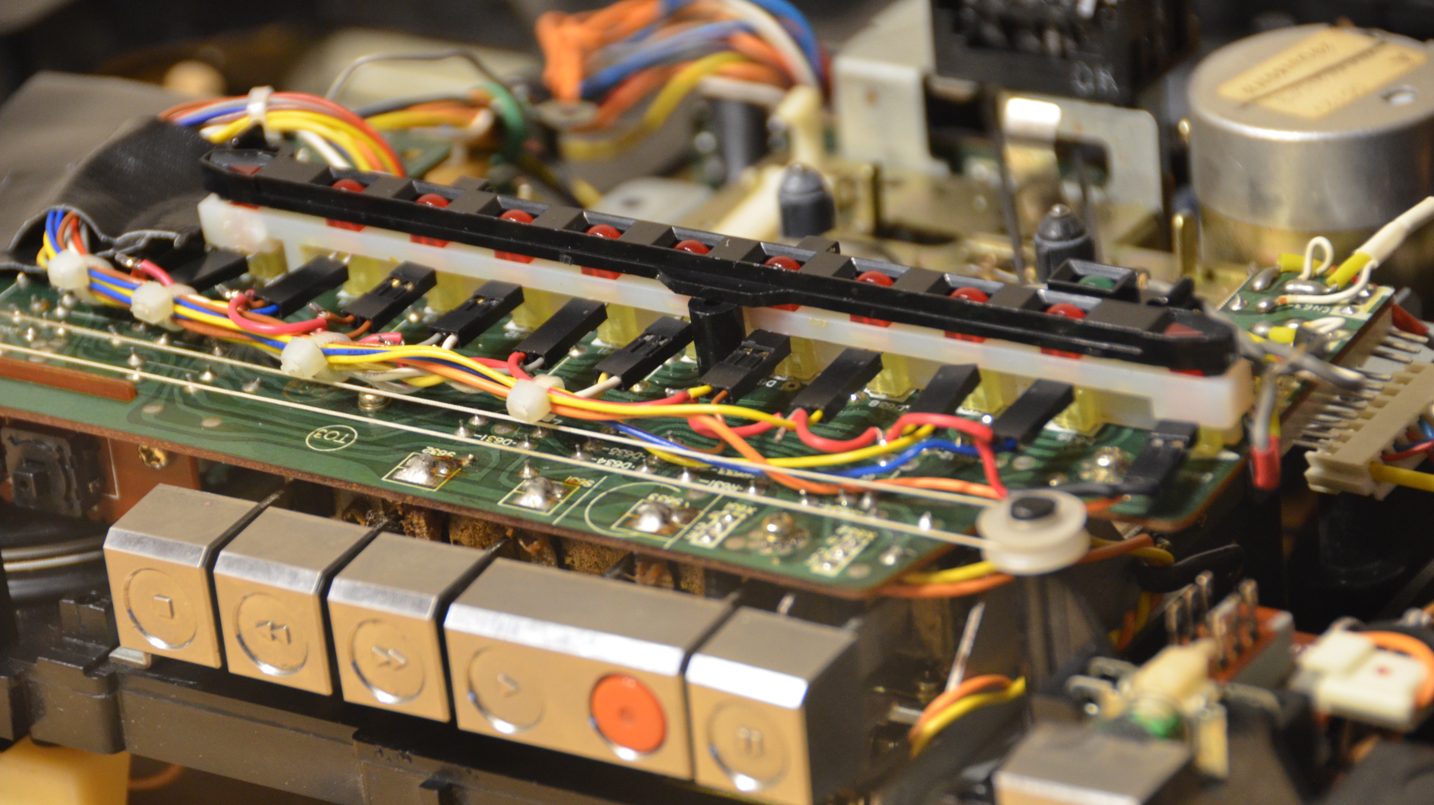
 Gettin' close!!