M70 LED meter mod

Status
Not open for further replies.

caution

Member (SA)
Mar 25, 2014
2,513
346
83
Boomboxery
Thanks! Turning out better than I planned :-)
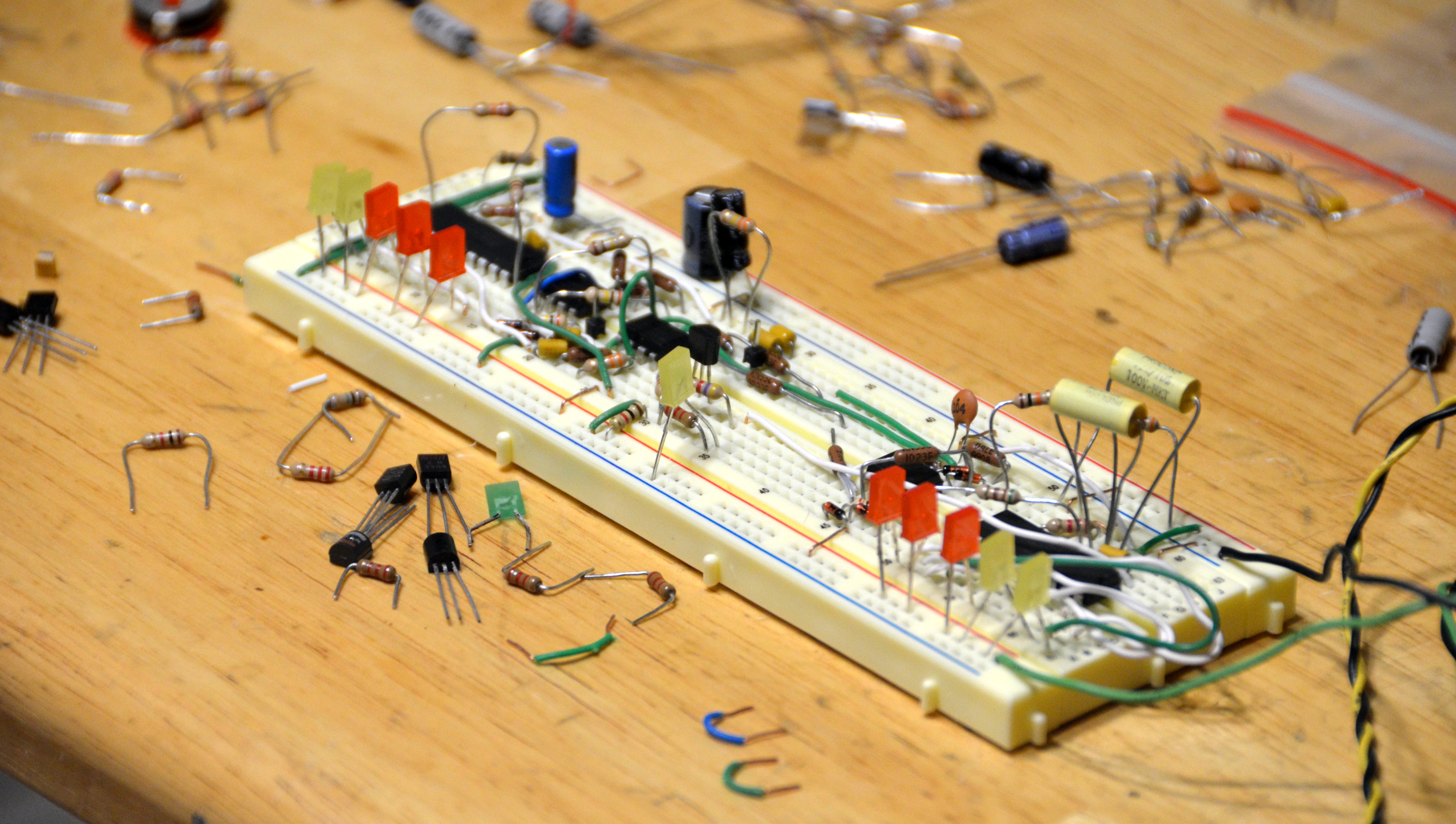
After a bit of adjusting, it looks like the VU boards will barely clear the big black tuning wheel. I still need to solder the other end of the wires to the LEDs. A few things I'm still unsure about though.

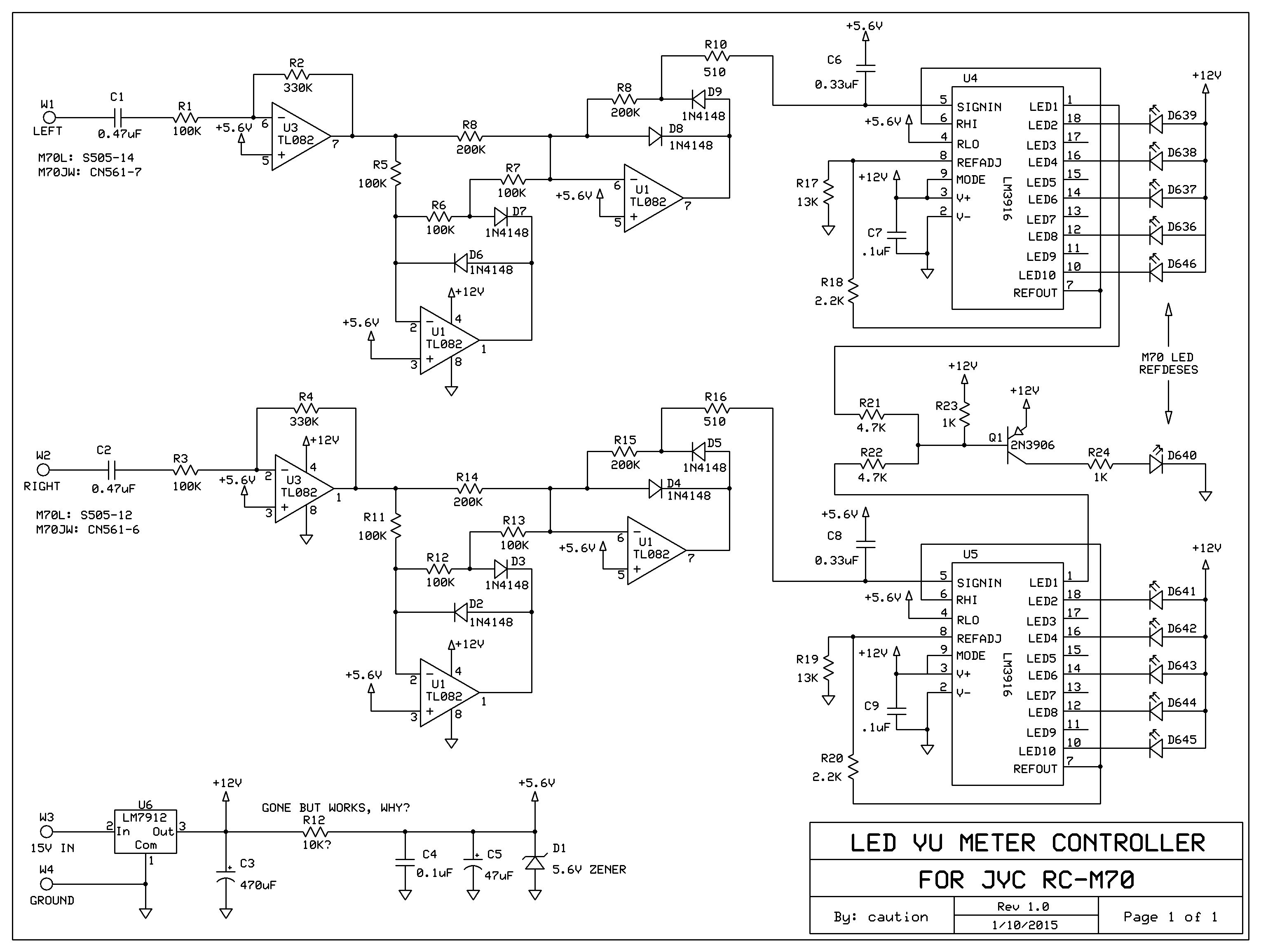
1. I need to combine the output of LED #1 from both chips for the center LED. I'm thinking of just shorting them together at the LED, but maybe it will get a little brighter when both outputs drive it, which may not matter enough to run them through an OR gate like this one.

2. I want the VUs to display the line level signal (the needles already vary by volume) but I have an M70L, which has an additional amp circuit for line out before it goes to the DIN jack. I'm assuming that this DIN amp output would be safer and more robust to use than doing what the JW models use, which seems to tie right off the line amp output with a 10K resistor for its line out jack.

3. I still need to figure out what value capacitors to hang off the input and output of the 9V regulator. I'm tapping straight off 15V and may have to run a few inches, I'm guessing that may matter in which values I choose.

Another 3-day work week, so I should have time to get this sorted soon!
 

caution

Member (SA)
Mar 25, 2014
2,513
346
83
Boomboxery
Tell me about it! I figured out why I wasn't getting much "bounce" last night. The next chip higher, LM3916, is optimized for audio signals, it uses the uneven dB stepping (-20, -10, -7, -5, -3, -1, 0, +1, +2, +3db) that I'm looking for. Currently I have the LM3915, which just does 3dB steps. Luckily the store near my house sells them.

Even with the right audio stepping, I'll have to decide which four to omit, since I'll have six LEDs and it has ten outputs. I'm thinking of omitting -10, -5, -1 and +1 to even it out, we'll see how that looks.
 

caution

Member (SA)
Mar 25, 2014
2,513
346
83
Boomboxery
I had to back out of the boards and get the breadboard out. As you may know, feeding raw audio into an LED meter is hardly readable, it flashes too quickly and too often. I built a basic peak detector as suggested in the LM3916 datasheet and looked beautiful. This is what I used.

The problem is that it uses a diode, which drops a bunch of my audio signal. If I'm not mistaken the line out signal is about 1.25V (p-p? RMS?) which is the same as the internal reference in the LM3916. Because of this, the first 3 to 4 LEDs are always on when there is no audio signal. Booooooo.

This would have made the circuit extremely simple, but if I just removed the first four LEDs (I only need six per side), it would be displaying for -3 to +3 dB, but when I tested out this configuration, it acted way too unresponsive for quieter stuff to be useful as a meter. I'm going to want at least the first or second LED. I only have a 23dB swing as it is.

I tried the only op amp-based peak detector in the datasheet that has a part available, but with no luck. The last time I worked an op amp was in college some 20 years ago so to say I am rusty is being generous. I did some looking around and figured out that I need to run the op amp in a single rail configuration since there are no negative rails in the radio.

I found this home audio test meter when trying to figure out how to power the op amp, and it uses a zener diode to create another rail. It even uses the same peak detector with the same widely available TL072 part I'm using, so I decided to try and modify this circuit, but it's not going well. Not smoke'n'flames bad, but still not getting me what I want. I use 9V and a higher line-in, and I don't have any tantalums.

I thought today that if I just used one op amp to create, say a 5:1 amplifier so that the swing going into the meter chip was much higher, thus minimizing the 0.7V from the equation, could that work? I could use just one op amp chip for both channels and do peak detection without op amps, eliminating a ton of parts. Not a huge deal but would be nice.

This has been an interesting project, but it's starting to take too much of my time trying to figure out, so it may have to get put back together unfinished for now :-(
 

Lasonic TRC-920

Moderator
Feb 16, 2010
14,130
108
48
55
Naples, Italy
Damn, I was really looking forward to seeing this thing come to fruition.

This site is going from collecting to creating! Great Stuff.

Hopefully you will get it all worked out at some point
 

blu_fuz

Moderator
Staff member
Jun 3, 2009
10,669
168
63
40
WI
Sounds like you have your hands full. Too bad the LEDs don't light up like you wanted, I really wanted to see this too.
 

caution

Member (SA)
Mar 25, 2014
2,513
346
83
Boomboxery
Better that you didn't read it haha. Clearly I bit off more than I could chew.

I've put a fair amount into this so I do intend on finishing it, but for now I just don't know how to do that. I've got a C100 sitting here waiting for my TLC.
 

SLO

Member (SA)
May 19, 2014
2,444
5
38
Inland Empire, Southern California
caution said:
Better that you didn't read it haha. Clearly I bit off more than I could chew.

I've put a fair amount into this so I do intend on finishing it, but for now I just don't know how to do that. I've got a C100 sitting here waiting for my TLC.
Keep the faith Caution, you worked your ass off on this. Don't give up bro. Hell I havent even changed a dam belt before Lol, my mind was boggled reading all this stuff, but in a good motivating way.
 

caution

Member (SA)
Mar 25, 2014
2,513
346
83
Boomboxery
Thanks SLO I did exactly that, I kept at this thing ever since I said I was going to put it aside. I couldn't stop thinking about it!

After many hours of researching, experimenting, cursing and head banging (the bad kind) I finally got what I wanted. I just had to try educated guesses at various cap/resistor values to get the right gain out of the buffer stage at the front end, watching where the signal peaked on the LEDs. Amazingly the precision full-wave peak detector circuits I built for each channel worked right the first time, but I had to work a bit at getting the center LED right. Turns out I could run the base of one transistor with both lines.

I've been tweaking the decay speed and am pretty happy with it, although there is a bit of a gap between the time the center LED and the rest of them switch, not really sure why because of the 10 outputs I only removed LEDs 3, 5, 7 and 9. Looks good enough I suppose.

Now to transfer it to a board...


http://youtu.be/AyWCEbFSXMY
 

Superduper

Member (SA)
Just curious why the sig-in for 3916 chip was pulled up with the regulator (which schem says was omitted?). I didn't see in the 3916 documentation to suggest that was necessary, at least not the datasheet from TI. Looked at TI's recommended full wave peak detector sample circuit using the LF353 opamp instead of your TL082, is done a bit differently than yours. Interesting....

precision full wave peak detector.jpg
 

BoomboxLover48

Member (SA)
Dec 3, 2010
5,762
275
83
Chicago, IL
I feel so happy to have a member like Caution here! Smart guy! Keep up the good work! :clap: :hooray:
All I want is a min of 10 LEDs on each side and five is not enough! They need to be colored too..

Sharp GF9696 was cheating big time... two of them made one LED. :lol: I was surprised to see that when I opened up the unit and took out the radio dials.
 

caution

Member (SA)
Mar 25, 2014
2,513
346
83
Boomboxery
That's the same one I used, I just put the DC blocking caps at the front end of the amp stage and tied the cap on the sig line to virtual ground (5.6V) instead of earth since it's a single supply configuration.

The 10K resistor is gone, not the entire regulator circuit. I couldn't figure out why I am successfully getting 5.6V for my virtual ground without pulling it high at least a bit. I was trying to use table 1 here to calculate a resistance for my 5.6V zener when I noticed after it was working that I had removed it on accident.

I tweaked on C6/C8 and R17/R19 to get a nice bounce, and in the end the caps were ten simes smaller than they should be, so there's probably an imbalance somewhere. Anything over a microfarad gives me a wicked decay. My thought was that it has to do with the fact that my virtual ground isn't exactly 6 volts (I couldn't find a 6V zener).
 

Superduper

Member (SA)
For the virtual ground, why not just use a simple voltage divider (like maybe [+15v] - [10k] - [virtual ground] - [10k] - [-0V]? Nothing to go wrong and always exactly 1/2 volts, especially since system voltage is likely to fluctuate anyhow?

Oh, and did that detector circuit require a dual supply? If not, did you try it with a single supply without the virtual ground?
 
Status
Not open for further replies.