VZ Issues: The Saga Continues

Status
Not open for further replies.

Gluecifer

Member (SA)
As a last ditch attempt to get my VZ-V20 going properly I took to motor out of my VZ-3000's record player and attempted the transplant. Now, I checked the 2000 and 3000 service manuals and both had the same motor. It's now come to pass that it looks like the VZ-V20 uses a DIFFERENT motor to the other two, or at least has a different pin out.

My question, in hope of saving the last remnants of my sanity, is can I change the contact points to make it work??

When the VZ-3000 motor is connected the turntable is constantly spinning but doesn't do much else. Also no LEDs light up on the turntable function display.


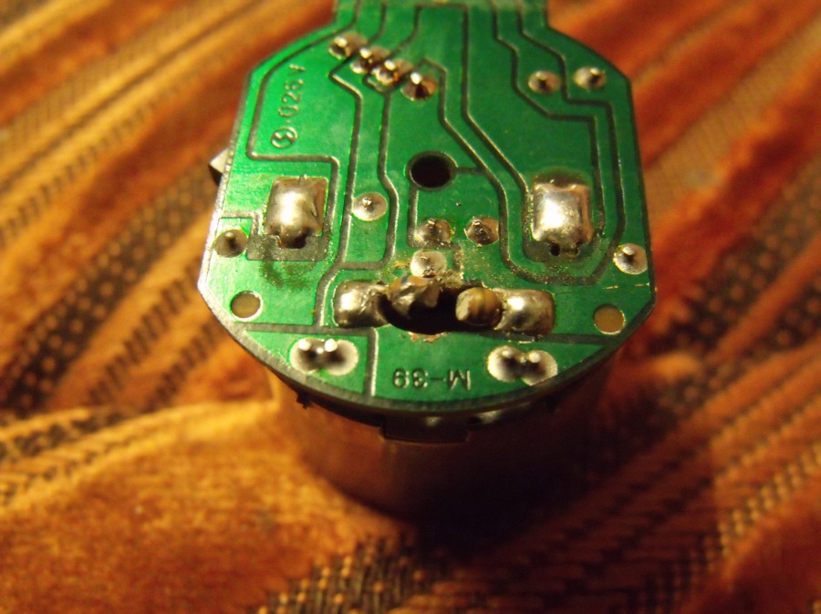
Here are the photos of the two different motors:

This is the CORRECT one that's buggered, these are it's pin outs
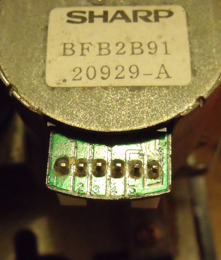
dscf3428.jpg


This is the one currently connected that likes to spin constantly and do nothing else
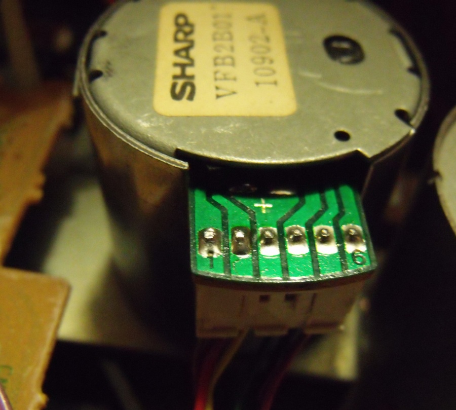
dscf3430.jpg


I can get more pix if it's of any use.

Help me boomboxery kenobi... you're my only hope.


Rock On.
 

Superduper

Moderator
Staff member
I suspect that the motor controller boards are different, more than just the pin-out. No service manual I've ever seen breaks down the motors internals so it wouldn't be easy to find the differences. The motor itself might be the same. If you look inside the motor, you'll find that there are some electronic componentry on that mini PCB. Perhaps if you disassembled the motor and swapped the controller board, you can get it to work for you. There is a danger, of course, that you could damage the motors in the process and end up with NO working motors. Also, it's quite possible that the controller board itself is what is bad. What's wrong with your old motor? Not working at all?
 

Fatdog

Well-Known Member
Staff member
Is the constantly-spinning turntable by design? If so, that sounds really retarded.
 

Gluecifer

Member (SA)
Bobby: the constantly spinning turntable shouldn't happen. It only happens with this new motor.

Norm: this is from my other VZ thread:

"Ok, through my complete ineptitude I think I've screwed the turntable drive motor.
I was trying to carefully adjust the speed and all of a sudden it started playing very fast.
I now can't locate the adjustment screw and it'll only play close to the correct speed if I stick something
metal in at the right angle that it bridges something inside.

Even still it's got a bit a warbling in the speed.."

I'm assuming now that dissecting the original motor and attempting to repair what's gone wrong inside it is my only option, my repairer dude said theres virtually no chance of getting a replacement that'll work. The only other option is to see if I can get another VZ through my mate in japan, get him to sacrifice it, and then send me the motor.


Rock On.
 

Superduper

Moderator
Staff member
I see. If the motor is already messed up, no reason not to take the back off and see if you can fix it. I suspect that the pot got damaged and changing it might fix the issue. If you can't find a replacement pot that'll fit inside (seeing as it's miniaturized), you might be able to feed some fine wires inside and mount a new pot externally for easier adjustment. Sounds like that is the only thing wrong with your old one.
 

Superduper

Moderator
Staff member
If you end up installing a new pot externally, try replacing it with one of the newer multi-turn (bournes) units instead. They give far more precise adjustments. Standard pots goes end to end in only 3/4 turn or so. The multi-turn ones will take about 20 turns to go from end-end in the range allowing for super precise adjustments.
 

alfie

Member (SA)
This doesn't bear well for my "seriously inexperienced" rebuild of a vz2500. :-O

I'll keep you all posted (help)
 

Gluecifer

Member (SA)
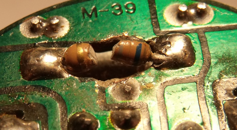
Well, it looks like there wasn't a pot there at all!

dscf3435.jpg


Looks like I broke that resistor!

Time to look for another one.. or possibly take out the one that's in the VZ-3000 motor...

Those tops aren't right bastards to get off those motors, I must say!


Rock On.
 

Gluecifer

Member (SA)
Interestingly the other motor lacks that resistor in that position.

One lesson we all can learn from this: DON'T adjust the VZ record player speed by adjusting the motor as you would on a tape deck motor. There's no pot in there!! Even on the VZ-2000 motor. It's got the little hole and everything, but there's no adjustment. If you need to adjust the speed there are two pots for each speed located on the main board of the record player mech..... which of course I found all too late.

I'm hoping theres going to be an easy way to work out the resistor I need, but I've never done anything like this before.


Rock On.
 

Gluecifer

Member (SA)
The resistor colours I can make out, in order:
Blue, Grey (missing section) Gold.

Is this of any help?


Rock On.
 

madbadger

Member (SA)
hi there, i have a app on my ipod that tells you the resistor colour code

ive put in what you said (apart from the missing colour) and heres what i have

blue gray black gold = 68 then its the icon shaped like a circle with 2 little feet, i think its the ohm icon? and then 5% tolerance

....... ....... brown ......= 680 ohm and 5% tolerance

...... ........ red ..........= 6.8 K and the ohm sign and 5% tolerance

...... ........ orange .....= 68 K ohm sign and 5% tolerance

....... ........ yellow ......= 680 K ohm sign and 5% tolerance

....... ........ green ......= 6.8 M and the ohm sign and 5% tolerance


........ ......... blue .......= 68 M and the ohm sign and 5% tolerance

........ ......... violet ....= 680 M and the ohm sign and 5% tolerance

....... .......... grey ......=6800 M and the ohm sign and 5% tolerance

....... ......... white .......= 68000 M and the ohm sign and 5% tolerance

........ .......... gold .......= 6.8 ohm sign and 5% tolerance


......... .......... silver .......= 0.68 ohm sign and 5% tolerance....


hope this helps you mate....

Kev
 

Superduper

Moderator
Staff member
So you made your own "hole"? :w00t: :lol: :lol:

Ooops. :blink: Sorry. Okokok. ..... I know that's not funny. :dunce: But I couldn't help it.

Alright, back to the VZ.

Rick. You really need to try to find the remants of the broken resistor to see if you can ascertain the color. I looked at the service manual and that resistor is shown and from the diagram, that resistor provides feedback to the motor driver transistor. Unfortunately, it does not indicate the value, probably because it was not intended to be disassembled during service figuring that the entire motor would be replaced instead. If I was guessing, I would guess either 68k or 6.8k, but it could be anything since it's in series with another resistor so the total resistance (1st + 2nd) is what is important and not the individual resistance of that resistor.

One solution, (recommended) without digging into the VZ3000 motor ---

Remove the old resistor and solder a couple of wires to where it used to be. Bring the wire out through that hole. Externally, clip a resistor onto the wire and see how it works. Start with a higher value (such as 680k). If it does not work as intended, then drop the value progressively by a factor of 10. So you would try 680k, 68k, 6.8k, 680 ohms, 68, then 6.8. Once you find the correct value, then just solder it externally and protect it with heatshrink tubing. I don't think the value would be 6.8mOhm and I don't think it would be lower than 6.8 ohm either. Resistors are cheap and this is how I would do it. So just solder the wires on and put that motor back together --- GO!
 

Gluecifer

Member (SA)
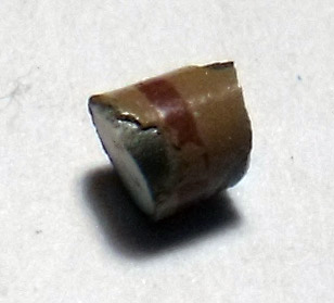
Ok, I can't believe it, but I found the missing piece of the resistor. More power to vacuuming rarely in my living room!!

And to think my sister nearly did on Friday. My blasterkarma is picking up again!

An the winning middle stripe colour is..........


RED!!

dscf3442_2.jpg


Or is that brown? It's a very reddy brown if that's the brown used.

Remaining resistor:

dscf3444.jpg


So the final colour code is Blue Grey Red (or brown) Gold.

I'm about to trawl through all my bits and pieces of broken radios to see what I can find.

Is there any leeway here Norm? I've got no idea about these values and such, but is there a similar
one that would do a good enough job or is this an absolute and must be exactly the same?


Rock On.
 

Gluecifer

Member (SA)
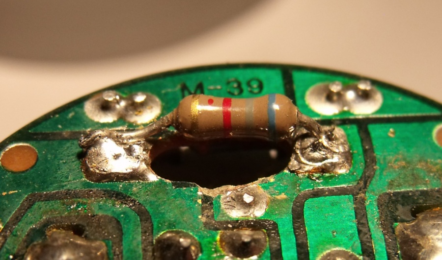
Well, I thought I was extremely lucky!
I found the resistor I needed and attached as below.

dscf3446.jpg


I'm presuming this is the wrong value resistor as I get this sound issue now, which was the same issue I had
when I'd broken the resistor and had to stick a screw in the motor to get the right speed.

[youtube]4LFB9uNBumg[/youtube] (Duran Duran's My Own Way).

I'm in uncharted territory here, so maybe that red 'dot' on the new resistor means it has a different value again?
Or perhaps the correct colour in the middle is brown?

I'll get back to hunting for more resistors and see what I can find.


Rock On.
 

Superduper

Moderator
Staff member
Gluecifer said:
Ok, I can't believe it, but I found the missing piece of the resistor. More power to vacuuming rarely in my living room!!

And to think my sister nearly did on Friday. My blasterkarma is picking up again!

An the winning middle stripe colour is..........


RED!!

[ Image ]

Or is that brown? It's a very reddy brown if that's the brown used.

So the final colour code is Blue Grey Red (or brown) Gold.

Is there any leeway here Norm? I've got no idea about these values and such, but is there a similar
one that would do a good enough job or is this an absolute and must be exactly the same
?

Rock On.

Rick. The problem with this is that the 3rd band is not a primary value number but rather, a multiplier. Therefore, if it's brown (and it does look brown to me) but computer color lies so you are the best judge of that. But again, if it's brown, then it's 680 ohms and if it's red, then the value is 6,800 ohms (or 6.8k). As you can see, that is a 10X difference in value so they are not interchangeable. It's one or the other.

What I would do is find another resistor in the boombox someplace with the exact same shade of red/brown color and measure the value with a meter. Then you'll know if that same color is red or brown. Different manufacturers and heat and age will tend to change colors so this would be the best way. BTW, use a new resistor Rick and don't use a used one. If you don't have any and need me to send you some, let me know and I'll send you a 680ohm as well as a 6.8kohm one too. However, I suspect that you may be too impatient to wait for it.
 

Superduper

Moderator
Staff member
BTW, did you break anything on the flip side too? Because in the schematic, I see that there is also another resistor, a diode and a transistor on that board. I also see what looks like a component lead soldered right next to that hole. Hopefully whatever is on the other side did not span the hole and also get "taken out" by the screw driver.

One other thing. If it is working like it was before, maybe that is correct. Because the speed control is actually taking place outside of the motor, apparently on the main board. So the adjustment would be off the motor on the mainboard anyhow.
 
Status
Not open for further replies.