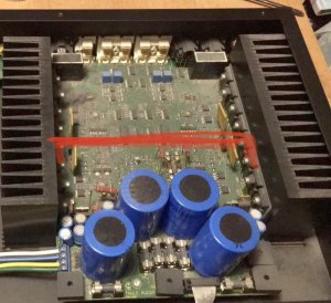
A friend of mine asked me to take a look at his Thule Spirit amp. The amp presented with distortion and the speaker protection circuit was clicking the relays often.
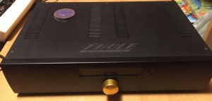
Outside, design is ... Danish simplicity from 1999. Inside, the schematic is very interesting, power amp entrance is basic but then the design gets really symmetrical, and not needing true grounding tap on the transformer means that parts in the power supply need to be really balanced. If anything goes wrong, whole switching part with lot of preamps get asymetrical voltages. Guess what...
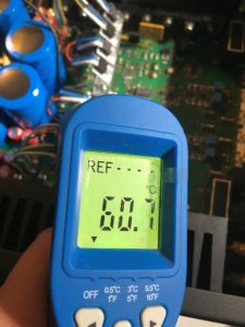
Danish were a bit stingy and used some not-so-top-of-the-line capacitors and soldering tech. Also, the use of 100mA LM317/337 in some cramped spaces, while dissipating quite a lot of power(up to 0.9W) resulted in some burn marks on the board.Finally, as far as I am concerned, using 1458 op-amp was a bit old fashioned even then - better op-amps were available, more appropriate for this really expensive amp (sorry, there are no 1458 in sound path).
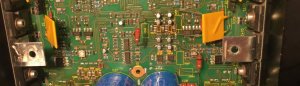
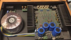
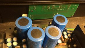
Quick look at the voltages revealed severe imbalance on REG1 and REG2, but not one part was visibly bad. Then again... one (out of four) 10 000uF filter cap had small smoke tail under it, not visible before de-soldering. So... I removed all electrolytic caps, both through-hole and SMD ones. About half of them did not had rated capacity and several were basically resistors.
I am waiting for new, 5000 and 10 000 hours, 105°C capacitors from Panasonic, Wurth and Vishay. I also ordered all new regulators, just in case (200mA versions). I have also re-soldered all power transistors, connectors, basically all large joints, and cleansed the board.
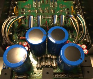
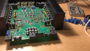
So far, this was easy fix. I'll see how it goes from here. In the mean time, you can take a look at the pictures, and perhaps you can give me an advice.
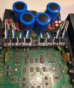
How can I improve cooling of regulators (marked with circles) in order to prolong the life of this nice amp? TO220 are so close to filter caps that I can't fit any cooler, and SMD reg's are so cramped, even the small coolers for RaspberryPI can't fit.


View attachment thule_audio_ia150b.pdf
Outside, design is ... Danish simplicity from 1999. Inside, the schematic is very interesting, power amp entrance is basic but then the design gets really symmetrical, and not needing true grounding tap on the transformer means that parts in the power supply need to be really balanced. If anything goes wrong, whole switching part with lot of preamps get asymetrical voltages. Guess what...
Danish were a bit stingy and used some not-so-top-of-the-line capacitors and soldering tech. Also, the use of 100mA LM317/337 in some cramped spaces, while dissipating quite a lot of power(up to 0.9W) resulted in some burn marks on the board.
Quick look at the voltages revealed severe imbalance on REG1 and REG2, but not one part was visibly bad. Then again... one (out of four) 10 000uF filter cap had small smoke tail under it, not visible before de-soldering. So... I removed all electrolytic caps, both through-hole and SMD ones. About half of them did not had rated capacity and several were basically resistors.
I am waiting for new, 5000 and 10 000 hours, 105°C capacitors from Panasonic, Wurth and Vishay. I also ordered all new regulators, just in case (200mA versions). I have also re-soldered all power transistors, connectors, basically all large joints, and cleansed the board.
So far, this was easy fix. I'll see how it goes from here. In the mean time, you can take a look at the pictures, and perhaps you can give me an advice.
How can I improve cooling of regulators (marked with circles) in order to prolong the life of this nice amp? TO220 are so close to filter caps that I can't fit any cooler, and SMD reg's are so cramped, even the small coolers for RaspberryPI can't fit.
View attachment thule_audio_ia150b.pdf