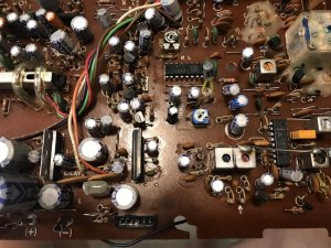
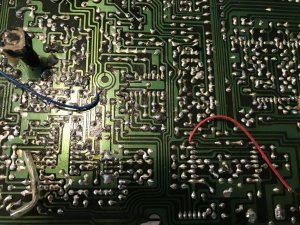
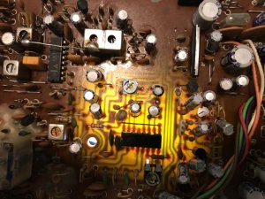
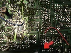
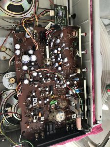
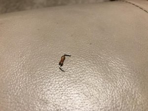
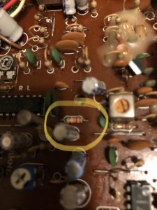
If the cap is bad, then it's bad so reinstalling won't fix anything. However, to be clear, when you tested the cap, you tested it in OHM mode and you got "0" or did you get infinity, no reading - - - - or something like that? You wouldn't be the first to make that mistake but zero is "0" and nothing (like as if nothing was connected) is not nothing, it is infinity. Zero is definitely shorted but most meters will almost never read zero. It would be more like 0.2 or some other low number. Even the leads have resistance so unless you rel out the built in resistance, you almost never get a true zero reading. Now, if you were getting no reading, then that's not necessarily indicating a bad cap. It might be perfectly fine. That's not how you test a low value cap.
As for your circuit, we can now see that your circuit indeed uses an MPX decoder chip, a Sanyo LA3361 (common chip). This is why you should always post extra details whenever possible so as not to waste time for others guessing. Here is block diagram of that decoder.
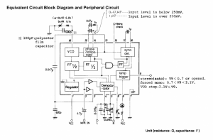
If you look carefully at the 1000p cap, which I presume is the one you removed, it has a caution sign next to it indicating that exact replacement is required. It states polyester but whatever was in there should be replaced with exact part. Mica, tantalum, ceramic, electrolytic, etc definitely shouldn't be used. Also look carefully and see that one leg is connected internally to the MPX decoders VCO (voltage controlled oscillator). This for sure requires a critical stable circuit. Also note that the is cap is connected to ground on the other leg creating a parallel circuit to the resistors. IF it were indeed shorted, that means that leg#16 would be grounded and no amount of adjusting of the resistors would have any effect. If that cap is truly shorted, you can certainly check now whether pin #16 is grounded with the cap in place. If yes, then the cap is definitely bad. If however you are getting some reading, say something between 6.8k and 16.8k, then the cap is likely fine or certainly not shorted.
Here is the sample circuit diagram. I am guessing that it should mirror your circuit quite closely.
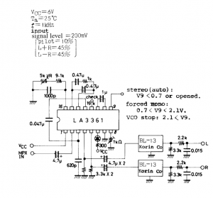
I suggest you compare the circuit to yours and see if your resistance network to pin 16 is working properly. In other words, check and verify that pin 16 to ground with an ohmmeter (radio powered off) reads a range consistent with the series resistors you have installed. The circuit is calling for 5k VR with a 9.1k fixed resistor, OR 10k VR with a 6.8k fixed resistor.
Also check out the notes regarding pin 9. According to notes, in stereo mode, should read less than 0.7v (or off). In mono, it should be between 0.7v and 2.1v. It sounds like the VCO will turn off if voltage exceeds 2.1v. It's worth confirming those numbers.


 . Thank you brother


