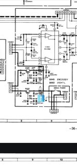
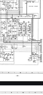
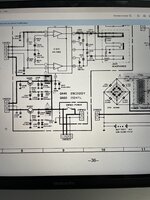
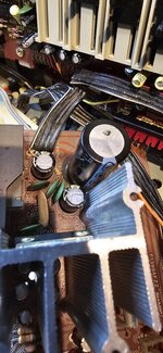
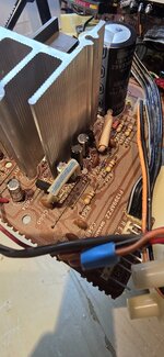
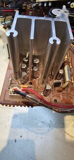
Yeah I checked time and time again it almost sounds like a transistor issue or ic I didn't check those tho so I will get back too you with thatDid you verify that all of the new caps are installed correctly +/- ?
Are those fusible resistor on that board, if so, did you check them?
Sharp GF-575E Audio Distorting pick up failure
- Thread starter Christopher1389
- Start date
-
- Tags
- sharp gf-575
You are using an out of date browser. It may not display this or other websites correctly.
You should upgrade or use an alternative browser.
You should upgrade or use an alternative browser.
- Status
- Not open for further replies.
If I were you, I would carefully desolder the HA1392 chip from the board, clean off the old, probably dried up heat sink compound, clean off all the corrosion from the pins, and reinstall with fresh heat sink compound. Audio that is unreliable and or cuts off after some time in operation could be from unreliable connection (corrosion) or from the chip over-heating from poor heat transfer to the cooling radiator. If you decide to do this, on reinstallation, first install the chip onto the heatsink with the tab screw to fix it in place, then install the heatsink and fasten it (if it is fixed in place with fasteners) and lastly, solder the pins in place. If you solder the pins before installing the heatsink, you'll risk the tab not being tight against the heatsink, or the screw tweaking the chip when torqued down. Also careful examination of solder pads should be performed or just touch up all of them.
Huffers
Member (SA)
That doesn’t sound right to me. The circuit diagram shows the voltages that you should have at each pin relative to ground. Also pin 12 should have 6v according to the diagram. Shouldn’t be grounded as it’s connected via a capacitor to ground, the capacitor should be open circuit so it shouldn’t show ground. Check that capacitor because that could be pulling it down.Thanks for the advice @Huffers so before I went on vacation I did just that I isolated the amplifier from the tuner and cassette deck and still get the same sound. I then tested the transistors Q181 q183 Just because they are in the path or the audio or circuit
And they tested all OK. So my Suspicion now is the dolby chips TA-7629P But unfortunately, I don't have the datasheet for them
so I tested them and one side doesn't read at all pin 9 10 11 13 14 15 16 and pin 12 is grownd is this right I haven't tested a ic before ? The gray line going into pin 4 is the Playback signal
OK so I think I've finally Found the issue fusible resistor R660 is not working when I connect the multimeter using ohms reading I get nothing but when I read it through diode continuity check it reads 15.5 so that must mean the fuse section is dead in this resistorDid you verify that all of the new caps are installed correctly +/- ?
Are those fusible resistor on that board, if so, did you check them?
R645 fuse resistor is reading OK as on ohms reading I'm getting 10.5 ohms and if I got to continuity diode check if getting continuity
r660 connects to the record play back swich and then to the main function selector board that selects radio and cassette
Thanks for the advice @Tinman
Attachments
OK so another update I just tested some transistors and I've found that Q645 NPN rectangular has reverse bias on collecter to base so I suspect it's gone defectiveOK so I think I've finally Found the issue fusible resistor R660 is not working when I connect the multimeter using ohms reading I get nothing but when I read it through diode continuity check it reads 15.5 so that must mean the fuse section is dead in this resistor
R645 fuse resistor is reading OK as on ohms reading I'm getting 10.5 ohms and if I got to continuity diode check if getting continuity
r660 connects to the record play back swich and then to the main function selector board that selects radio and cassette
Thanks for the advice @Tinman
I have some concerns that you aren't testing the components correctly or aren't fully understanding how components work or are tested. You also continually state "I've tested this, or I've tested that." What exactly does that mean and how did you test and conclude that an IC or other component is good or bad? You said you tested the Dolby chip but one side doesn't read all all??? What exactly does that mean? O volts? Infinity continuity? Short circuit? Also did you have your negative meter probe in a true ground? One user followed up that pin 12 is not ground, is that where you were placing the negative probe when you conducted your test? You indicated that you tested the fusible resistor R660. But you said you got 0-KΩ as the reading. But then you say you also checked it with diode check on your meter. I don't understand under what condition or situation you would ever check a resistor with a diode check function, and you even say you read 15.5. 15.5 what? What exactly would you expect to discover diode checking a resistor? Just FYI, a fusible resistor is just a resistor that fails open and is flameproof. It is in all other aspects, simply a resistor and there's no fuse component. Also in post#22, I made a recommendation but it is unclear if you ever tried that. Being that you recapped the board, it would seem like a no-brainer to remove the amp IC and clean off all the corrosion that is clearly present on many of those pins. Checking for continuity is not useful. That's because voltage drop often does not happen until you have current flowing. Therefore, when a high powered device is not powered up, the connections could have continuity. High resistance and cut off may not manifest until current flows. I would definitely do that FIRST to ensure that the corrosion of those pins haven't migrated to the solder joint.
May I also suggest you test to see if you are getting normal audio output through the line-out jacks. If the line out jacks are outputting a signal, then you can basically preclude all of the circuits before that point. Note that the line-out jacks are very close to the amplifier input connections. Also, be advised that your issue affects both channels. That means you need to focus on a component or circuit that would affect both sides. The amp chip itself is a dual amp IC. That means a failure there can definitely affect both channels. Prior to the amp chip, there are 2 parallel audio circuits. L & R. Focusing on individual caps or resistors that only affect one channel is probably misguided and could lead you to bark up the wrong tree. Is it possible that the same capacitor that serves one channel also has a sister cap on the opposite mirrored channel that simultaneously failed? Possible, yes. Likely, not very.
If you are asking for advice, and if you follow any/some/all advice, I suggest you clarify what advice you followed and what you did not, and post the results. Nobody knows how to advice further if they don't know exactly what you did.
Lastly, you stated that you found an issue with Q645. Did you do your testing with the component in the circuit. Please post B/E/C voltage readings (do it carefully, live) so we can evaluate it. Negative probe at ground, positive probe taking measurements from each of the pins. The ground should be system ground, and not a random spot. Typically, dark bold lines on a schematic often represent the ground bus.
OK thanks for the advice I apologise if I'm hard to understand as I struggle with ADHDI have some concerns that you aren't testing the components correctly or aren't fully understanding how components work or are tested. You also continually state "I've tested this, or I've tested that." What exactly does that mean and how did you test and conclude that an IC or other component is good or bad? You said you tested the Dolby chip but one side doesn't read all all??? What exactly does that mean? O volts? Infinity continuity? Short circuit? Also did you have your negative meter probe in a true ground? One user followed up that pin 12 is not ground, is that where you were placing the negative probe when you conducted your test? You indicated that you tested the fusible resistor R660. But you said you got 0-KΩ as the reading. But then you say you also checked it with diode check on your meter. I don't understand under what condition or situation you would ever check a resistor with a diode check function, and you even say you read 15.5. 15.5 what? What exactly would you expect to discover diode checking a resistor? Just FYI, a fusible resistor is just a resistor that fails open and is flameproof. It is in all other aspects, simply a resistor and there's no fuse component. Also in post#22, I made a recommendation but it is unclear if you ever tried that. Being that you recapped the board, it would seem like a no-brainer to remove the amp IC and clean off all the corrosion that is clearly present on many of those pins. Checking for continuity is not useful. That's because voltage drop often does not happen until you have current flowing. Therefore, when a high powered device is not powered up, the connections could have continuity. High resistance and cut off may not manifest until current flows. I would definitely do that FIRST to ensure that the corrosion of those pins haven't migrated to the solder joint.
May I also suggest you test to see if you are getting normal audio output through the line-out jacks. If the line out jacks are outputting a signal, then you can basically preclude all of the circuits before that point. Note that the line-out jacks are very close to the amplifier input connections. Also, be advised that your issue affects both channels. That means you need to focus on a component or circuit that would affect both sides. The amp chip itself is a dual amp IC. That means a failure there can definitely affect both channels. Prior to the amp chip, there are 2 parallel audio circuits. L & R. Focusing on individual caps or resistors that only affect one channel is probably misguided and could lead you to bark up the wrong tree. Is it possible that the same capacitor that serves one channel also has a sister cap on the opposite mirrored channel that simultaneously failed? Possible, yes. Likely, not very.
If you are asking for advice, and if you follow any/some/all advice, I suggest you clarify what advice you followed and what you did not, and post the results. Nobody knows how to advice further if they don't know exactly what you did.
Lastly, you stated that you found an issue with Q645. Did you do your testing with the component in the circuit. Please post B/E/C voltage readings (do it carefully, live) so we can evaluate it. Negative probe at ground, positive probe taking measurements from each of the pins. The ground should be system ground, and not a random spot. Typically, dark bold lines on a schematic often represent the ground bus.
and sometimes struggle to describe things in a way you will understand but I'm always willing to learn new things and try my best
We all got to learn for somewhere
I will get back to you when I've done more tests
Last edited:
OK is when I first looked at the amplifier board I could visually see that two big capacitors had bulged and the previous owner had replaced a blown one. So I figured I may as well order them all and replace them on that board so I did in doing so I also noticed that the IC HA1392 had corrosion on some of the pins so I DID desolder the ic and cleaned all corrosion from them. I then tested continuity with the pins of the ic between each solder joint BUT I did not test with voltage going through the ic. So when I got the new capacitors I put them all into there correct places and cleaned all the switchesI have some concerns that you aren't testing the components correctly or aren't fully understanding how components work or are tested. You also continually state "I've tested this, or I've tested that." What exactly does that mean and how did you test and conclude that an IC or other component is good or bad? You said you tested the Dolby chip but one side doesn't read all all??? What exactly does that mean? O volts? Infinity continuity? Short circuit? Also did you have your negative meter probe in a true ground? One user followed up that pin 12 is not ground, is that where you were placing the negative probe when you conducted your test? You indicated that you tested the fusible resistor R660. But you said you got 0-KΩ as the reading. But then you say you also checked it with diode check on your meter. I don't understand under what condition or situation you would ever check a resistor with a diode check function, and you even say you read 15.5. 15.5 what? What exactly would you expect to discover diode checking a resistor? Just FYI, a fusible resistor is just a resistor that fails open and is flameproof. It is in all other aspects, simply a resistor and there's no fuse component. Also in post#22, I made a recommendation but it is unclear if you ever tried that. Being that you recapped the board, it would seem like a no-brainer to remove the amp IC and clean off all the corrosion that is clearly present on many of those pins. Checking for continuity is not useful. That's because voltage drop often does not happen until you have current flowing. Therefore, when a high powered device is not powered up, the connections could have continuity. High resistance and cut off may not manifest until current flows. I would definitely do that FIRST to ensure that the corrosion of those pins haven't migrated to the solder joint.
May I also suggest you test to see if you are getting normal audio output through the line-out jacks. If the line out jacks are outputting a signal, then you can basically preclude all of the circuits before that point. Note that the line-out jacks are very close to the amplifier input connections. Also, be advised that your issue affects both channels. That means you need to focus on a component or circuit that would affect both sides. The amp chip itself is a dual amp IC. That means a failure there can definitely affect both channels. Prior to the amp chip, there are 2 parallel audio circuits. L & R. Focusing on individual caps or resistors that only affect one channel is probably misguided and could lead you to bark up the wrong tree. Is it possible that the same capacitor that serves one channel also has a sister cap on the opposite mirrored channel that simultaneously failed? Possible, yes. Likely, not very.
If you are asking for advice, and if you follow any/some/all advice, I suggest you clarify what advice you followed and what you did not, and post the results. Nobody knows how to advice further if they don't know exactly what you did.
Lastly, you stated that you found an issue with Q645. Did you do your testing with the component in the circuit. Please post B/E/C voltage readings (do it carefully, live) so we can evaluate it. Negative probe at ground, positive probe taking measurements from each of the pins. The ground should be system ground, and not a random spot. Typically, dark bold lines on a schematic often represent the ground bus.
And then put power to the unit and when I powered up the unit it would play music again but sounded a little distorted and then It totally slipped away and turned to a static sound it sounded like a fm station that has no signal. So I then did some more testing I then started isolating components from the main amplifier such as disconnecting the radio section from the unit and disconnecting the cassette deck and to no avail it still sounded the same as I suspected a Previous post suggested this. I also checked if the same static sound could be heard from the line output and it was. there was nothing from the cassette or radio there Neither
So I started looking at the service manual Schematic and looking at the Playback signal and figured that the problem must be past the function selector switch going towards the amp. So I traest it and it connected to some ics alc IC 181 and Dolby ics TA-7629P But I had never tested.ICs before so I thought pin 12 was grownd brain fog moment
So I've just looked now and pin 1 is grownd because of the bold black line on the schematics as you said so I will retest later today
So then someone Suggested to check the Fusible resistors, on the amplification board So I tested them with ohms reading and one tested at 10.5 ohms but the Fusible resistor R660 tasted at 0 ohms
I then checked diodes using diode check And they all test OK
Huffers
Member (SA)
hi
So some observations.
The dark line is not ground (unless I’m looking at it wrong).
The connector CNP602 is the main power supply.
Pin 1 is ground and pin 2 is positive. Regarding your testing of R660 and R645.
R645 should read 10ohms so that appears to be correct. R660 should actually be 15 Ohms, so there may be an issue. The problem is testing components while they are still on the board, as something else might impact it. I suggest taking out R660 and retesting and still
Seeing if it is 0 Ohms (dead short).
If so then that component is faulty. If it reads ok at around 15ohms then there is probably something else on the board pulling the circuit down to ground, I would check capacitors C663 and C660 to make sure they are ok. Again it is easier to test them out of the board. They should be open circuit (very high resistance) across them.
Attachments
Huffers
Member (SA)
As superduper said fusable resistors are just resistors they do not have a polarity therefore diode test is not valid. You should get the appropriate resistance reading across the resistor regardless of which way around you test it. For instance R645 is a 10ohm resistor. If it’s working it should read 10ohms. If it’s blown then will read open circuit. They typically do not go short circuit (O ohms). I assume you are testing R660 whilst on the board. Therefore it is probably something else on the board which is giving you the 0 ohm reading.OK is when I first looked at the amplifier board I could visually see that two big capacitors had bulged and the previous owner had replaced a blown one. So I figured I may as well order them all and replace them on that board so I did in doing so I also noticed that the IC HA1392 had corrosion on some of the pins so I DID desolder the ic and cleaned all corrosion from them. I then tested continuity with the pins of the ic between each solder joint BUT I did not test with voltage going through the ic. So when I got the new capacitors I put them all into there correct places and cleaned all the switches
And then put power to the unit and when I powered up the unit it would play music again but sounded a little distorted and then It totally slipped away and turned to a static sound it sounded like a fm station that has no signal. So I then did some more testing I then started isolating components from the main amplifier such as disconnecting the radio section from the unit and disconnecting the cassette deck and to no avail it still sounded the same as I suspected a Previous post suggested this. I also checked if the same static sound could be heard from the line output and it was. there was nothing from the cassette or radio there Neither
So I started looking at the service manual Schematic and looking at the Playback signal and figured that the problem must be past the function selector switch going towards the amp. So I traest it and it connected to some ics alc IC 181 and Dolby ics TA-7629P But I had never tested.ICs before so I thought pin 12 was grownd brain fog moment
So I've just looked now and pin 1 is grownd because of the bold black line on the schematics as you said so I will retest later today
So then someone Suggested to check the Fusible resistors, on the amplification board So I tested them with ohms reading and one tested at 10.5 ohms but the Fusible resistor R660 tasted at 0 ohms
I then checked diodes using diode check And they all test OK
Last edited:
The dark line is not ground (unless I’m looking at it wrong).
Pin 1 is ground and pin 2 is positive. Regarding your testing of R660 and R645.
R645 should read 10ohms so that appears to be correct. R660 should actually be 15 Ohms, so there may be an issue. The problem is testing components while they are still on the board, as something else might impact it. I suggest taking out R660 and retesting and still
Seeing if it is 0 Ohms (dead short).
If so then that component is faulty. If it reads ok at around 15ohms then there is probably something else on the board pulling the circuit down to ground, I would check capacitors C663 and C660 to make sure they are ok. Again it is easier to test them out of the board. They should be open circuit (very high resistance) across them.
It appears that the OP is using a schematic diagram that was originally in color but scanned in black/white, which converted fat red lines into black. This is why I was a little concerned that the OP was unable to determine ground by reading the schematic.
As for the fusible resistor, originally the way I read his comment, he checked R660 and said he got "nothing". But when you quoted the post, I think it said 0, I don't know how that changed. There is a difference. "Nothing" is non specific, but zero is something else. Usually fusible resistors will fail O/C, which is why they are fusible-type. However, if he's saying it's shorted, although that should be addressed, as a practical matter, it does not affect the operation of the regulator that it protects and therefore, should not be the cause of his issues, unless it's shorted when powered off, but drifts off to infinity when powered up. The fact that he's stating it was "nothing" in the ohms test but 15.5 in the diode test? That doesn't comport. I personally think a re-test is in order here to clarify the findings. Otherwise bad data in = bad data out.
OK is when I first looked at the amplifier board I could visually see that two big capacitors had bulged and the previous owner had replaced a blown one. So I figured I may as well order them all and replace them on that board so I did in doing so I also noticed that the IC HA1392 had corrosion on some of the pins so I DID desolder the ic and cleaned all corrosion from them. I then tested continuity with the pins of the ic between each solder joint BUT I did not test with voltage going through the ic. So when I got the new capacitors I put them all into there correct places and cleaned all the switches
And then put power to the unit and when I powered up the unit it would play music again but sounded a little distorted and then It totally slipped away and turned to a static sound it sounded like a fm station that has no signal. So I then did some more testing I then started isolating components from the main amplifier such as disconnecting the radio section from the unit and disconnecting the cassette deck and to no avail it still sounded the same as I suspected a Previous post suggested this. I also checked if the same static sound could be heard from the line output and it was. there was nothing from the cassette or radio there Neither
So I started looking at the service manual Schematic and looking at the Playback signal and figured that the problem must be past the function selector switch going towards the amp. So I traest it and it connected to some ics alc IC 181 and Dolby ics TA-7629P But I had never tested.ICs before so I thought pin 12 was grownd brain fog moment
So I've just looked now and pin 1 is grownd because of the bold black line on the schematics as you said so I will retest later today
So then someone Suggested to check the Fusible resistors, on the amplification board So I tested them with ohms reading and one tested at 10.5 ohms but the Fusible resistor R660 tasted at 0 ohms
I then checked diodes using diode check And they all test OK
(1) No need to explain or apologize for AHDD, but details matter, they really do, especially if you aren't a seasoned and experienced tech. There's no way for us to check your work if you don't fully explain in explicit and specific detail, like how you actually did a test. For example if you say "I tested all these and they are all OK", should we trust that all the things you checked were done correctly? Because if we begin to make such presumptions and rule those components out, then any advice we give is only as good as the "presumptions."
(2) I looked at your facebook images and videos. I hope that you followed my instructions on how to remount the amp IC onto the heatsink before placing then into the holes and soldering. Otherwise, the back surface will likely be cocked and not get proper contact with the heatsink. Also I recommended that the old hard compound be cleaned and replaced with new heatsink compound. The video doesn't show this, only the heatsink removed and almost all the pins corroded.
(3) The thing about poor connections and corrosion is that they often don't show high resistance without a load which is how you would typically test them with an ohmmeter. Once powered up you cannot test resistance with an ohmmeter. High resistance that manifests at that point would have to be tested for (live) voltage drop across the connection. Google if you want more info on how to do this. But if you simply just clean off all connections and reinstall with fresh solder, this ensures that isn't an issue.
(4) When you say that the regulator transistor was testing improper bias, it's totally unclear what you mean. That's why I asked for a B/C/E voltage check on that regulator (live). These zener transistor regulators all work in very predictable manners and before you condemn that transistor, I'd like to see the voltage readings because I can tell at a glance whether it is working properly.
(5) In your facebook images, I see that the amp board has a series of capacitors. I can't read all the writing on the caps but I hope you ensured that thereplacements are all the same voltage ratings or higher than the ones you extracted. Also, I've never seen those silver cans before, are they reliable brands? Also, I see something a bit concerning.... on your original board, the negative markings on the cans and on the PCB are all very clear and marked in the conventional manner. However, on the first can you installed, I see the black stripe mounted on the (+) side. Unless these are way weird caps with reversed markings (+) marked with black bands, then it appears at least this cap is reversed in polarity. If this is true and you followed up by installing all of the caps in this manner, then they are all installed reversed polarity. If this is true, and you decide to replace them again, use new ones, don't reuse electrolytic caps that have been installed backwards, as they could already have been damaged internally.
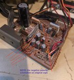
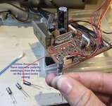
The last photo was just to see if they fit well(1) No need to explain or apologize for AHDD, but details matter, they really do, especially if you aren't a seasoned and experienced tech. There's no way for us to check your work if you don't fully explain in explicit and specific detail, like how you actually did a test. For example if you say "I tested all these and they are all OK", should we trust that all the things you checked were done correctly? Because if we begin to make such presumptions and rule those components out, then any advice we give is only as good as the "presumptions."
(2) I looked at your facebook images and videos. I hope that you followed my instructions on how to remount the amp IC onto the heatsink before placing then into the holes and soldering. Otherwise, the back surface will likely be cocked and not get proper contact with the heatsink. Also I recommended that the old hard compound be cleaned and replaced with new heatsink compound. The video doesn't show this, only the heatsink removed and almost all the pins corroded.
(3) The thing about poor connections and corrosion is that they often don't show high resistance without a load which is how you would typically test them with an ohmmeter. Once powered up you cannot test resistance with an ohmmeter. High resistance that manifests at that point would have to be tested for (live) voltage drop across the connection. Google if you want more info on how to do this. But if you simply just clean off all connections and reinstall with fresh solder, this ensures that isn't an issue.
(4) When you say that the regulator transistor was testing improper bias, it's totally unclear what you mean. That's why I asked for a B/C/E voltage check on that regulator (live). These zener transistor regulators all work in very predictable manners and before you condemn that transistor, I'd like to see the voltage readings because I can tell at a glance whether it is working properly.
(5) In your facebook images, I see that the amp board has a series of capacitors. I can't read all the writing on the caps but I hope you ensured that thereplacements are all the same voltage ratings or higher than the ones you extracted. Also, I've never seen those silver cans before, are they reliable brands? Also, I see something a bit concerning.... on your original board, the negative markings on the cans and on the PCB are all very clear and marked in the conventional manner. However, on the first can you installed, I see the black stripe mounted on the (+) side. Unless these are way weird caps with reversed markings (+) marked with black bands, then it appears at least this cap is reversed in polarity. If this is true and you followed up by installing all of the caps in this manner, then they are all installed reversed polarity. If this is true, and you decide to replace them again, use new ones, don't reuse electrolytic caps that have been installed backwards, as they could already have been damaged internally.
View attachment 59483
View attachment 59482
This is how the board looks now and I checked multiple times before applying powerThe last photo was just to see if they
(1) No need to explain or apologize for AHDD, but details matter, they really do, especially if you aren't a seasoned and experienced tech. There's no way for us to check your work if you don't fully explain in explicit and specific detail, like how you actually did a test. For example if you say "I tested all these and they are all OK", should we trust that all the things you checked were done correctly? Because if we begin to make such presumptions and rule those components out, then any advice we give is only as good as the "presumptions."
(2) I looked at your facebook images and videos. I hope that you followed my instructions on how to remount the amp IC onto the heatsink before placing then into the holes and soldering. Otherwise, the back surface will likely be cocked and not get proper contact with the heatsink. Also I recommended that the old hard compound be cleaned and replaced with new heatsink compound. The video doesn't show this, only the heatsink removed and almost all the pins corroded.
(3) The thing about poor connections and corrosion is that they often don't show high resistance without a load which is how you would typically test them with an ohmmeter. Once powered up you cannot test resistance with an ohmmeter. High resistance that manifests at that point would have to be tested for (live) voltage drop across the connection. Google if you want more info on how to do this. But if you simply just clean off all connections and reinstall with fresh solder, this ensures that isn't an issue.
(4) When you say that the regulator transistor was testing improper bias, it's totally unclear what you mean. That's why I asked for a B/C/E voltage check on that regulator (live). These zener transistor regulators all work in very predictable manners and before you condemn that transistor, I'd like to see the voltage readings because I can tell at a glance whether it is working properly.
(5) In your facebook images, I see that the amp board has a series of capacitors. I can't read all the writing on the caps but I hope you ensured that thereplacements are all the same voltage ratings or higher than the ones you extracted. Also, I've never seen those silver cans before, are they reliable brands? Also, I see something a bit concerning.... on your original board, the negative markings on the cans and on the PCB are all very clear and marked in the conventional manner. However, on the first can you installed, I see the black stripe mounted on the (+) side. Unless these are way weird caps with reversed markings (+) marked with black bands, then it appears at least this cap is reversed in polarity. If this is true and you followed up by installing all of the caps in this manner, then they are all installed reversed polarity. If this is true, and you decide to replace them again, use new ones, don't reuse electrolytic caps that have been installed backwards, as they could already have been damaged internally.
View attachment 59483
View attachment 59482
Attachments
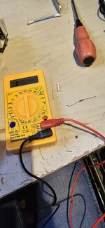
OK so I have removed the Fusible resistor from the board and give it a quick test and it just reads 1 ohm I can only get something when I go to 2000k ohmsAs superduper said fusable resistors are just resistors they do not have a polarity therefore diode test is not valid. You should get the appropriate resistance reading across the resistor regardless of which way around you test it. For instance R645 is a 10ohm resistor. If it’s working it should read 10ohms. If it’s blown then will read open circuit. They typically do not go short circuit (O ohms). I assume you are testing R660 whilst on the board. Therefore it is probably something else on the board which is giving you the 0 ohm reading.
Attachments
At 1 ohm, it’s shorted. At 2000k range, probably reads 0? Anyways, it should be replaced but even if it were shorted, the regulator it’s protecting should still function. Unless there is an over current condition and the resistor failed short, in which case the regulator could be toast too. Please post the readings on that transistor leads. Once those are posted, we can conclude if the transistor is bad.
Do you have access to a signal tracer or signal injector? Those would make a huge benefit to signal tracing.
Do you have access to a signal tracer or signal injector? Those would make a huge benefit to signal tracing.
Unfortunately I don't have a signal tracer as of yet but i hope too get one soonAt 1 ohm, it’s shorted. At 2000k range, probably reads 0? Anyways, it should be replaced but even if it were shorted, the regulator it’s protecting should still function. Unless there is an over current condition and the resistor failed short, in which case the regulator could be toast too. Please post the readings on that transistor leads. Once those are posted, we can conclude if the transistor is bad.
Do you have access to a signal tracer or signal injector? Those would make a huge benefit to signal tracing.
Testing PN junction on the npn transistor
Transistor q660 base to emitter reads diode drop at 832 black on emitter and red on base if I reversed the leads Red on emitter and black on base I get nothing that's how it should be
And Base to collecter black lead on collecter and red on base 830 and if u reverse the leads I get nothing
caution
Member (SA)
Pretty sure that "1" you see on your meter, in your picture, is just indicating that the value you're trying to measure is too high for the range you're set to (200 ohms). If it was a legit reading, I'd expect to see the reading be right-hand justified and include more digits.
Resistors don't go down in value when they fail, they go up, usually to infinity/open circuit.
Resistors don't go down in value when they fail, they go up, usually to infinity/open circuit.
Ugh, looks like once again, there is the suspicion of readings that maybe not right. You said you had an analog meter? Set to lowest range and try again. 0 or 1, and OL (over limit, or infinity) makes all the difference.
- Status
- Not open for further replies.


