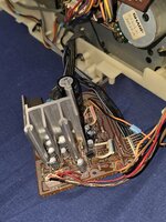
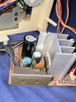
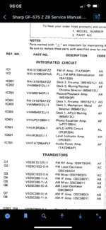
Interesting. Will see if I can dig out a schematic for the Ha1392. I have had a few of these go in other boxes. sometime they go because the electrolytic capacitors around them on the audio circuit go short and short out the IC.
Although judging by the static I am thinking the main power amp ok (as if it was the chip I don’t think you would get that level
Of audio). I would think that it’s something feeding in before the amp that is causing it.
Maybe try to isolate some of the inputs from the radio cassette, aux. And see if you can remove the interference to narrow down the issue.
The interference sounds like radio interference, does the sound alter at all if you rotate the tuner dial even if only slight? Maybe try isolating the tuner circuit first.
There are also some pre-amps I believe on this box so you could check this out.
A box of this age I would certainly check out the electrolytic capacitors as they have a tendency to fail. You can check with an ordinary multimeter or you can get a transistor test like the LCR-T7 pretty cheap. As well as measuring capacitance (multimeter should have this) they should also be open circuit on a resistance test.