Sanyo M9998 Restoration.

Status
Not open for further replies.

SGrant

Member (SA)
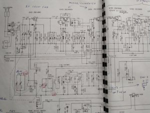
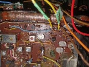
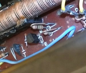
As per the photo, which shows Q104's three legs and the "B" and "E" characters on the board. This has confused me about Q104's pinouts. The following is based on assuming that the board characters are misleading. No pun intended.

Band selection AM, voltage readings on Q104:
B: 0.11
C: 6.42
E: 7.5

According to the circuit diagram, they are supposed to be:
B: 1.14
C: 7.13
E: 0.54

Band selection FM, as per circuit diagram:
B: 0.5
C: 6.16
E: 7.2

Given my ignorance about these things, treat the following as speculation.

This would suggest Q104 is not getting enough voltage on B and also amplifying too much.

I've been getting normal AM reception and tuning by connecting the vom between ground and C. So is the vom supplying the AM frequency signal or is it increasing amplification by adding current?

Are D309 and Q104 both bad? D309 is hidden under the blue wire in the photo, but it looks fine.IMG_20240310_132807280~2.jpg
 
Last edited:

thinkchronicity

Member (SA)
I've never checked a diode before, so I didn't know my vom had that function. The reading across D309 is 777. I don't know what that means. It's a DS442X.
0.777v would make sense. Then you're meant to check it in the opposite direction.

i hope someone else can chip in and solve your issue Steve. I can't quite fathom the schematic, and anyway family crisis has turned my brain to mush this year.
Good luck and never give up!
 

SGrant

Member (SA)
I hope your family matters have resolved for the better. I've had some time to take a break from this (AM band not working on Sanyo M9998) and consider the logic of the issue. Please correct me where that logic may be astray.

The AM band works ok with a vom set on resistance and the leads connecting preamp transistor Q104 - Collector to ground. I can change volume and stations using the radio's controls.

What may have led me seriously astray is thinking the vom was acting as an antenna. I stupidly overlooked that the vom has no way to select stations or change volume. And the vom was not connected to the base of Q104 which is connected to the AM antenna.

So. The radio's antenna must be connected correctly, and the main amp must be working properly. This is supported by the fact that bridging every associated portion of the circuits using jumpers did not fix the problem.

The circuitry connected to Q104 - C is a little too complex for me to fully understand, but it should feed some current from common to Q104 - C. I think a vom set to resistance would provide current. But the vom also has this effect when set to measure voltage. This doesn't make sense to me.

It also appears the function of S101 - 4 on the AM setting is to connect L101 to Q104 - C while bypassing R302.

And if all of this makes sense, Q104 is defective. It appears to be fine though. I think it's worth replacing it.
 

SGrant

Member (SA)
I replaced Q104, C131 and D309, and installed a jumper in case there was a bad connection between Q104 and T101. The AM band still does not work. So I'm giving up on this. I won't be using the AM band on it anyway and it's not worth more of my time just to add to its value. My thanks who assisted with this.
 

Superduper

Moderator
Staff member
The problem with your situation is that I don't trust your readings. You are claiming that the Q104C reads 6.42v while Q104E reads 7.5v with the Q104B only reading 0.11v. If you understand transistors, this scenario isn't really possible with an NPN transistor. The source of the emitter current generally comes from the collector, so the transistor output can't read higher than the source. Then there is only 0.11v at the base. This small base voltage doesn't even overcome the device turn on point of approximately 0.5V to 0.6V (higher) than the emitter. In other words, with the Base voltage at 0.11v, the transistor isn't even turned on, ergo, ZERO amplification and emitter should read or be very close to zero. (Unless) 1: the emitter is reading (negative voltage potential) sufficient to overcome the base turn on voltage, or (2) If your readings are true, then that means that the emitter current comes from elsewhere. However, if you analyze the circuit, you will see that the emitter goes to ground through a resistor, so that path does not provide positive current. When emitter readings are unusually high, the first thing to investigate or suspect is whether that resistor has opened, but even if it has, the emitter should not exceed the collector voltage. The other possible current source path is through a capacitor, which if working properly blocks DC. So no DC current through that path either. Or are you actually measuring AC? The term gobblydegook basically states garbage-in, garbage-out. In other words, without good data, any analysis or result of such analysis would be garbage so if the data is obviously problematic, it often is not worth proceeding further until the source of that erroneous data can be clarified. Are you relying on the board markings to determine the transistor pin-outs? Board silkscreen are often wrong from the factory. Technicians see errors like this all the time. If you see funky readings that don't comport with reality, your houston, we have a problem mode should always kick in and you should try to uncover the reasons for the impossible readings. Did you actually look up the datasheet for that transistor to see what the manufacturer of that component says is the pin out assignment, and did it match? Also, when measuring transistor voltages, is the boombox actually set to AM or FM? It makes a difference. Perhaps those readings are supposed to be with the set placed into FM mode. Typically when a multi-band tuner circuit diagram is available, it will provide a table listing voltages with the device set to the band, the local/dx, the mute or stereo settings in particular positions. Lacking such chart, it would be a mistake to presume that the readings specified applies to both AM and FM settings. In other words, a non-problem might appear to be a problem because the diagram failed to include the voltage with the tuner set to the particular you are testing. I don't doubt that your tuner is not working, and that you are able to get it to "sort of" work when you probe a component lead with your meter. However, something isn't right with your data or your hookups or your measurements. It's not really possible if the circuit is (as per the circuit diagram).

Lastly, you often take long breaks between posts. Let me tell you right now that each response takes time for the responder to consider and research. That means we need to look up the schematic and service manual. For me, that means I need to dig up the paper manual to study before formulating a response. This often takes considerable time. But these long breaks between responses is problematic because when you respond days or weeks or months after the fact, nothing is fresh in our minds anymore. In order to make additional responses, we need to study the entire thread all over again because we likely forgot what your dilemma was, what you did, what measurements, and then we need to once again pull a service manual. This gets old really quick because we are all busy people and nobody likes to do redundant work. I'm sure you are busy too, so it's not a knock, just the honest truth.
 

SGrant

Member (SA)
I appreciate your frankness.

There have been long pause in my efforts on this thing because resolving the AM band has been so disappointing. Compounding the difficulties are that there is no chart for voltage readings for different band settings. It appears the readings were done with FM selected, but that is not for certain. I believe the pinouts for Q104 are incorrectly silkscreened. And this portion of the circuit diagrams involves an area in a paper fold that was lost when it was scanned.

I take an ample portion of the blame, for going beyond what my level of expertise justified tackling.

Thank you for putting so much time into this. It is a valuable service to the community. I won't bother you with it any more since I'm too fed up with it to waste any more time on it. It is now our home stereo, hooked up to external speakers for listening to FM stations and cassettes. The AM band is no problem except for giving up on the challenge and eventual loss of value to a collector.
 

BoomboxLover48

Boomus Fidelis
I never used to tune AM on any of my boomboxes and realized that it is not working on 3 of my M9998 I have in my collection!
I checked AM after seeing your link here.
After lots of struggle with belts replacement I had tape play on one of mine but after say 5 minutes, it slowed down and stopped.
FM stereo works on two but the third one works with no stereo separation.

No more evasive surgery and organ transplant if the tape is not working!
 

SGrant

Member (SA)
From looking up reports and ads for the M9998 it seems AM band failure is common if not typical. It's too bad no one has reported fixing it because chances are it's the same cause for most of not all of them. I sure know what the problem isn't.

I considered having a professional work on it, but if I were such a person I'd have to charge more than the thing is worth because it's so difficult to work on them. (Yes, I knew.) I'm just thankful mine is back together with most of it working.

I too had residual speed problems after replacing the belts. I blamed the motor, but it looked like too much trouble to open it up to lubricate it. Finding a replacement looked like a challenge also. Not to mention removing the motor. I may have gotten some lubricant into the spindle end. But the problem turned out to be the three 45-year old cassettes (out of 50) that I chose to test it with, were bad tapes that don't work in any player no matter how much work I do on those 3 cassettes.

I've got the M9998 set up for home use now with external speakers. One thing I learned is it has to have the FM antennas out, and there is a switch that has to be set to internal antenna. Otherwise FM performance is dismal. I then found that at low volume and "ext" speakers selected, one channel is quiet or silent at low volume. With higher volume or the speaker switch at "int", there is no problem. With the speaker switch at "int + ext", there is more of a problem. So something to do with the speaker switch is going on. It's not the volume control because both channels work fine at all volumes using just the internal speakers. Perhaps the antenna switch just needs cleaning, but I haven't tried that yet. It's something you could check on yours.

I do have to open it up again for the umpteenth time because after "final" reassembly I found I've bent the dial pointer. Great. So I can give the speaker switch a shot of cleaner while it's open.

I'm also going to figure out how I can plug the earphone jack from a cell phone or mp3 player into the M9998 so I can play mp3's on it. The options are: ext in jacks, mic in jacks or phono in jacks. Or get an FM transmitter for the player.
 

Superduper

Moderator
Staff member
If the silkscreen is wrong, a real possibility, but you can ascertain if this is true simply by following my suggestion earlier which is to determine the transistor number either physically or by the schematic, download the datasheet for that component, and the pin-out assignment descriptions will be a part of the datasheet. Compare and see if it's correct. If your diagram is missing a chunk that you need, let me know exactly what you are looking for and I might be able to help with that. Waay back, Frank, a user which I forget his screen name suggested that lots of sanyo's had small ceramic caps that would go out. Some of the IF transformers also had small caps integrated inside the canister or embedded below or something. If those failed, you might have to open up the can to change those (although I'm sure that back in the day, the entire can would be replaced). You can't just tack a cap to the board underneath because the failed cap might not have completely failed (open) or might have changed characteristics and you'd need to take them out of circuit. One thing you might want to consider is that meter leads or probe tips might have some capacitance. If probing your transistor causes it to work again, that might be something you'd want to consider.
 
  • Like
Reactions: SGrant

Superduper

Moderator
Staff member
Oh and if you feel defeated by tackling a tuner issue, don't let this get you down. You won't be the first as tuner diagnostics is a difficult craft and beyond the abilities of novices, especially if you don't have the full range of diagnostic tools and options available to you. Tinkering with them often leads to worse outcomes, although on AM, the issue is usually due to failed components, many of which have exacting characteristics and obsolete.
 
  • Like
Reactions: SGrant

SGrant

Member (SA)
Q104 is shown in the centre top of the attached photo, just below the AM antenna. That is the original but the question here is whether it is labelled correctly. My later vom tests were using the pinouts from the spec sheets, not going by the board lettering. In any case I replaced it with a new one and that didn't fix the problem.

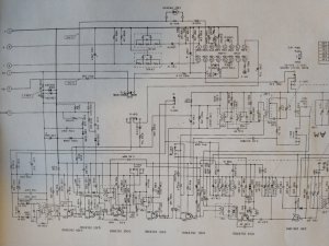
And the incomplete circuit diagram. There is a smaller scale version in the manual, but it's not complete either.

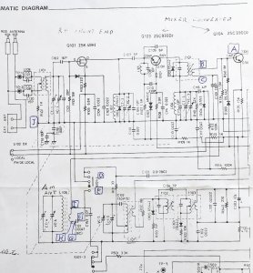
I also replaced C131 and D309, and installed a jumper (A to B) in case there was a bad connection between Q104 and T101.IMG_20240308_104758335~2.jpg


IMG_20231223_190643116~2.jpg

IMG_20240315_132510259_HDR~2.jpg
 

Superduper

Moderator
Staff member
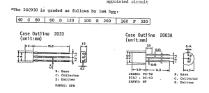
So the cap you replaced is a tiny ceramic one right? Also where did you get the transistor from? Don’t tell me eBay, they’re basically all fake. This transistor has been obsolete for decades. You can’t really find true OEM Sanyo 2SC930 anymore. Furthermore, did you get the D suffix version? It makes a difference, the hfe between the “no suffix” and “D” version is 50% greater beta. I know that the parts list doesn’t specify but on the schematic, it looks like it’s saying 2SC930D. Lots of Chinese parts are just restamped generic transistors. You test them and they test good but they have different characteristics and in the tuners, characteristics are critical. As for the missing portion, if you aren’t specific, I can’t help you with whatever information you’re missing.
 

SGrant

Member (SA)
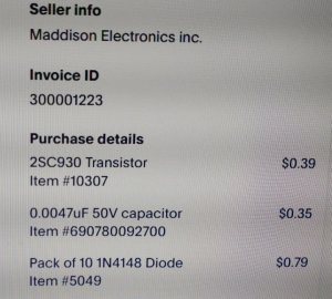
Attached are the order information for the parts
and the more complete version of the circuit diagram. Also a cropped version to isolate the missing content. It is a vertical "seam" that includes S101-3 and S101-4.

On the circuit diagram Q104 is indeed designated as 2SC930D², while it is just 2SC930 in the parts list.

The capacitor I bought is a tiny ceramic one. (Minimum quantity for the diode from this source was 10.)
IMG_20240509_190738716~2.jpg

IMG_20240509_190738716.jpg

IMG_20240509_190609885~2.jpg
 

Superduper

Moderator
Staff member
The replacement transistor you used may not work for you, and may be too weak in beta (hfe). The specs in the datasheet show the amplification differences between the different suffixed versions. Most of the time, if a suffix is specified, it is there for a reason. Click on thumbnails for expanded view of the images.

IMG_9294.jpg Screenshot 2024-05-13 at 1.57.14 PM.png
 

SGrant

Member (SA)
I've done a lot of online searching and although I have found 2SC930's with various "D_" suffixes, I have not found 2SC930D² as it is soecified on the circuit diagram. Will any 2SC930D_ be better than the one I installed? Or does it have to exactly match 2SC930D²?

In the Parts List it is called: "2SC930 Conv", further confusing the matter.
 
Status
Not open for further replies.