Been a hell of a nigthtmare, especially the rebelting part...
but finally succeeded to restore and add bluetooth to this non AUX-in device.
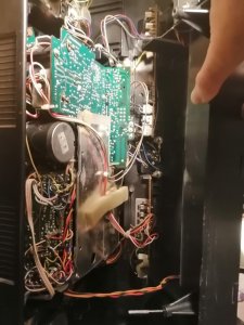
Step 1 :
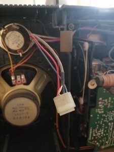
removing the back cover, taking care not to forget to photograph every and all cable that needs to be detached before detaching it (there are a lot of those !),
Step 2 :
removing the black frame, held by different sorts of screws, it holds the tuner/deck/... be careful to photograph each and every screw and cable holder (black thing), because they are there for a reason... and to remove the microphone cable and plug and the 3 pins for the amss indicator leds - pink blue white on the bottom , and a a 5 pin plug that s on the bottom right hand side (and photogaph everything before removing). Dont forget to pull up the power and dial light button and turn them to keep them up !
Step 3 : rebelting..........a living nightmare...
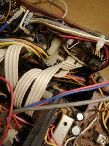
On the backside : remove the 2 screws that hold the tape deck switches (white knobs visible), remove the back pcb (with a lot of flat cables and a few pins - again you ll have to undo some cable holders so be mindful to photograph ANYTHING you undo before undoing it and to photograph where cables pass - they are a very tight fit.
Uncut some cable holders so you flip the pcb 45 degrees and more to access the back of the tapedeck
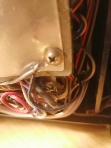
Remove 3 screws holding a plate to get access to the belts.
Step 3 bis : clean any black detoriated sticky gelified belt residue (in my case it was allover the place) with alcohol
Step 4 : put in new belts (I use a "manicure" set, it has some accessories that help to hold belts in place and help tu pull them over the axes
Step 5 : reverse the operation, dont forget to re-attach any cables that were previously attached so they dont get in the way of the mechanisme and cant touch any belts or parts of the deck
Step 6 : while at it, I removed the front panel (first remove the 2 screws that hold the AMSS led pcb, to give it thourough clean
IMPORTANT : DO NOT press REW for some reason it blocks when everything isnt in place, can lead to breaking the REW button lever , same for the other buttons, so when the deck is out and nothing is powered on : when you feel resistance on a deck button : do not insist.
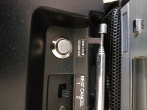
Step 7 : while at it, I replaced the lightbulb (that was still working but was permanently on) with 2 green leds (and their appropriate resistors), and slipped 2 3mm leds iinto the space between the Stereo/power/dolby leds to light the VU-meters. and added a button to permanently light the dial. I used a simple on/off button. The dial light cable is a red + white cable that is "stuck" right above where the tuner dial wire goes. I left that in place and took the blue wire (With a pin on the tuner pcb where it plugs into), that goes from tuner pcb to power switch (from where it goes to the dial light switch), thus putting the button in "paraellel" with the original dial light /battery check button. This way the original button stil works, and lights up the dial light and indicates battery level , the button I added only lights up the dial light (without battery check being activated).
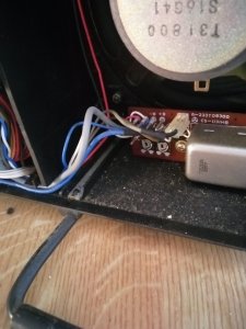
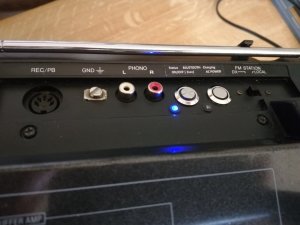
Step 8 with all being back in place, after putting back all screws, re-attaching all cables,... and putting back frontplate and the all the other parts... I only needed the back cover to install a bluetooth module and its power adapter in it. I removed the pcb for phono / din / ... (this is the LU version so it has din and not AUX
 ), found the "line in" on the din and used to to solder the bluetooth line out to it. The DIN connector (on the internal pcb) had 2 copper contactors that permanently connect and are disconnected when a din plug is plugged in. In order to be able to record to tape and since I m not using a DIN plug plugged in but only its connections on the pcb, I put a slice of elctricians tape on the larger one of the connectors so they dont make contact).
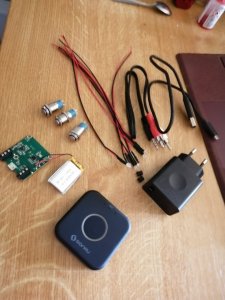
Step 9 : Prepping bluetooth module : I use a basic bluetooth 5.0 usb bluetooth module with only a "status / answer call / on off" mulitonction button on it. I only use its pcb and not the entire black box thing it comes in. It has status micro leds to wihich i soldered new leds in parallelm, and then i burn through and remove the original microleds, thus giving me 2 leds, 1 for status and 1 for battery charging (module comes with an internal rechargeable battery). Parellel wired the only multifonvtion button so i can wire a momentaneous external button instead.
Step 10 : bluetooth power : I parelled a basic 220v to usb adaptor to the 220v power inlet (In my experience this avoids interference), opened a bluetooth cable and cut the +5v cable, which I have pass through an on/off (12V 2A) button to have a power on/off button for charging bluetooth battery and or have it run on ac power instead of its internal battery.
Step 11 : drilling holes....to put my buttons and leds. Since I use 12mm buttons and 3mm leds, I use a wood dril of 12mm and 4mm (I like to put in led holders, so need the extra mm), in my experience these allow to drill quite accurately and mildly withouth melting of cracking the plastic, and since they have a "pin" in the center they allow accuracy. I tape both sides before drilling though, makes for a nice and clean drillhole.
Step 12 : Put it all in place : soldered wires to the buttons and leds before fixing them in place, addes some hotglue on the backside so nothing can move afterwards. Put some rubber doublesided tape on the small battery (bluetooth) and stuck it to the back cover (minding it has airflow), and aluminum taped it for heat dissipation, glued the bluetooth module to a 2 mm rubber pad and then to the back cover, plug everything in (usb / jack for audio that was soldered priorly to the DIN IN and DIN GND).
Step 13 : guide all cables, plug everything into the back cover (this is where the photos comme in handy), re-attach the back cover, try everything out and here s the result :
Last edited: