Sanyo M-X720k smashed power supply boards FIX

Status
Not open for further replies.

Superduper

Moderator
Staff member
5 years ago, another member asked me to fix his M-X720. Problem was disovered to be a toasted power/function switch and later on, issues on the main PCB (probably the dolby chip). Anyway, as luck would have it I guess, rather than have me rebuild his main switch, he found a beater box and had it shipped to me. From this, I was able to restore his boombox. The beater was in bad shape but it would not power up. Turns out the power supply was shattered. Initially it didn't look too bad. Until you flipped it upside down, then you can see the evidence of repairs that were attempted. Even from the component side, if you look closely, you can see the cracks. Boards like this can't really be "fixed" because of the design. Basically, the transformer is screwed onto 2 screw towers, but sideways. It's a very heavy transformer. The transformer is also soldered onto the PS board, which is further anchored onto a 3rd screw tower. Basically the transformer relies on the PCB to keep it from pivoting down making the PCB a structural part of the transformer mounting system. Poor design in my opinion. A big shock and the twist will shatter the PCB which is exactly what happed here. There is external evidence of damage to the case, so the drop/shock was signficant.

ex-1a.jpg

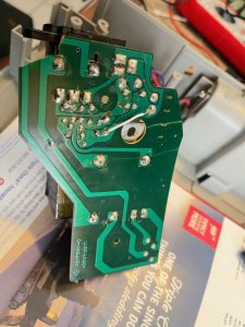
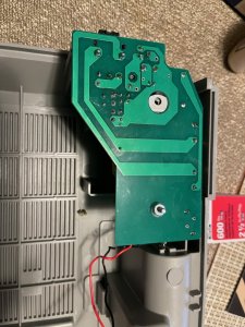
Here is the PCB from the top. Doesn't look too bad, but if you look very carefully, you'll see signs....

ex-1d.jpg

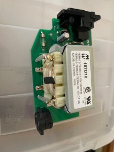
Transformer removed, Oh oh, can see some cracks more clearly now.


ex-1b.jpg

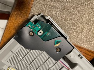
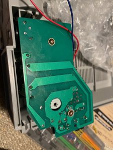
Ok, now we can see the attempted repairs. Didn't work apparently. No wonder, with it looking like humpty dumpty, theres no way any trace breaks will retain integrity because that transformer weighs over 2 pounds, almost a KG. When that flexes, trace repairs just breaks again.

ex-1c.jpg

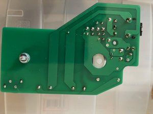
Board cleaned up. But this isn't going to be reused. No way any fix is going to be reliable.
 

Superduper

Moderator
Staff member
Well 5 years later (earlier this year), member BoomboxLover48 contacted me and asked me to "fix" his M-X720k power supply. I didn't really know how bad it was or what was wrong with it so I said, sure, send it over. Here is what it looked like.

ex-2a.jpg
Uh yeah, there's less trace repair, but the board has definitely suffered massive damage. There's even a chunk missing (upper right corner).

ex-2b.jpg

Transformer removed. Yeah, lots of damage. Component integrity is also a concern seeing the leads would have been stressed by being tugged apart and twist.

ex-2c.jpg

Bottom side, mostly cleaned up. The remainder of components I didn't bother to remove. They won't be reused.
 
  • Love
Reactions: BoomboxLover48

Superduper

Moderator
Staff member
Clearly, the structural design weakness I observed in the first example has an effect on more boomboxes than the low reports suggests. What are the chances? I wasn't informed of any external signs of damage to the boombox itself, was told it was minty. I think any shock to the boombox risks shattering the PCB, especially as those old resin boards age. Looking at it, I noticed a couple of shortcomings in the design too. The service manual schematic shows 2 fuses, but none were present in the actual board. The lack of fuses probably contributed to the transformer being toast too. The secondary winding was open circuit. The board itself has holes punched for what looks like fuse holder slots, but there were no traces on the board leading to those holes. The filter capacitor on the PS was only 33uf. Tiny for a PS on a 15V boombox (although I surmise that additional filtering caps would likely be present on the board itself since that just seems too low). Nevertheless, there's no reason not to have improved filtering at the output leads so I decided to upgrade that cap a bit larger. 220uf should do it. There is also a AC blocking diode to protect the batteries. But it's only a 1-amp diode. 1 amp x 15 volts = 15 watts meaning that the diode is at risk if the boombox is running at 15 watts input. Remember, all of the battery power runs through that diode. Additonally, standard diodes have a voltage drop of .6-.7v. That means 15 volt battery pack will only be able to pass 14.3 - 14.4v to the main board. Then there's the rectifier diodes. They're rated at 1.7A. All right thats probably ok but I've had to replace the rectifier diodes on a Sanyo M9994 before, so I'm guessing that their choice of component safety margins are rather slim. So I decided to make the following changes to the circuit, and make a new PCB.

Change 33uf capacitor to 220uf
Change AC blocking diode to 6A schottky diode (which only has a .3v voltage drop and more robust than the orig 1A).
Remove the 4 rectifier diodes and replace with a 6A full wave bride rectifier module
Add 3 amp fuse to the secondary circuit (was non existent)
Add 3 amp fuse to the battery supply circuit (was non existent)
Install modern off the shelf transformer, using Triad F6-12 which is a 12.6V 31.5VA unit.

The modified circuit is attached. However, I unfortunately drew the rectifier upside down so the + and - is reversed on the schematic. If you decide to copy it, make sure to note that error. I'm not going to bother to redraw it.
 

Attachments

  • modified circuit.pdf
    1.5 MB · Views: 8

Superduper

Moderator
Staff member
Ok, to the PCB. I've made many circuit boards in rectangle shape but given the weird shape of this board, the fact that my mind is now ultra lazy compared to when I was younger, and that the layout accuracy needs to be precise in order for everything to fit in place, especially the sockets and transformer mounts, I had to enroll the assistance of CAD guru Caution to help draw it up. He did a phenomenal job implementing the layout exactly like I envisioned. Many thanks and kudos to him :bow::bow::clap::smooch:for taking time away from his busy life and agreeing to assist with this. The new board is FR4 which is fiberglass reinforced and much stronger than the old board. Also, any unused straggler holes on the original board was omitted to improve structural strength and avoid weak spots where cracks could form. Once the design was complete, I ordered the board to be cut by a PCB manufacturer. In the old days, I would use blank boards and etching solution to make and although I still have a quart of the solution, it's probably no good anymore and I'm too old to deal with that, especially with better options. You just need to pay some and have lots of patience. New board arrived and it's a beauty.

new_mod1.jpg

NEW blank board.

new_mod2.jpg

Installed the sockets and other components. The caps tested out of specs... will later be changed before returning this to BoomboxLover48.

new_mod3.jpg

Installed the transformer. Temporary screw is installed to prevent it from shifting on the PCB before final installation.

new_mod4.jpg

Another view of the completed PCB.

new_mod5.jpg

Bottom view.
 
Last edited:

Superduper

Moderator
Staff member
Initial testing shows that the output on AC is about 20.7VDC. (The Sanyo M-X720k is a 15V box). This compares almost identical to a JVC RC-M70 chassis that I had lying around open, and that tested to be 20.6VDC. Frankly, this is the transfomer that I recommend. I've also used this same transformer on a Sanyo M9994 which is a 12V box, didn't have any issue with it.

However, Royce was uncomfortable with the voltage that high. Ultimately, it's his box and all I'm doing is building him new PS. His comfort level is all that matters since he's going to be the one installing it, and I'm not intending to warranty anything so I decided to order another transformer with a lower voltage. The Triad was not available from either Mouser or Digikey so I decided to get the Hammond 187D10 instead. The voltage is 10VAC instead of 12.6VAC but the VA is essentially the same as the Triad xformer and plenty since it’s higher than the factory rating (31va compared to factory 26va). Physical dimensions and mounting layout is the same as the Triad branded one. After that was swapped and new multilayer ceramic caps were installed, I got a voltage of 15.6VDC at the outputs with no load. This has been sent back to Royce who has installed it.

Notes. I didn't like the fact that the transformer mounted on tiny screw tower tips with hardly any landing area to resist rotation. Again, Caution comes to the rescue and helps me draw up some screw tower sleeves so I could order them 3D printed in nylon. They aren't very large but does provide a slightly wider landing for the transformer mount. Also importantly, the sleeves help reinforce the screw tower tips to reduce tendency for the tips to split. Anyone that's worked on enough boomboxes knows what I'm talking about, where the tips of screw towers start to crumble. These sleeves are glued on flush to the 2 screw towers where the transformer bolts to.

Conclusion. Sanyo didn't design the transformer mounting system very well and it is prone to shattering the PCB if a box is dropped. If shipped, even with bubble wrap and foam peanuts, if dropped in just the right way, this exact damage can occur, even if there is no outward signs of damage to the box or carton. It is the shock that does the damage by twisting the transformer on the mount and transfering that twist to the PCB, not from physical impact to the shell. I suspect that these aren't the only 2 examples out there with this exact issue, and some may have already been sent to boombox heaven because of this. If you have a X720 with this issue, even if you spliced all the broken traces, you may want to replace that PCB anyway. boxes with PS pcbs repaired by gluing and trace repairs are not going to hold up when shipped again. There's no way that glued board will hold back a 2+ pound transformer mounted on the side of the box with constant downward rotational stress. Luckily, when the PCB order was placed, there was a minimum order requirement, so there's a couple extra boards here. PM me if you need one. You should have good, or better yet, advanced de-soldering skills. The components don't matter but the sockets are made of plastic and can't take much heat. If you melt those or damage them, your power supply will no longer work and replacements simply aren't available. Also, the transformer windings likewise can't take too much heat because the windings usually are typically coated with laquer only which serves as the insulation. If too much heat is applied, the insulation could break down and the windings will short. If you are in USA, we might be able to arrange shipping your board here so I can swap out the components for you if you are unable to or uncomfortable to do that.
 
Last edited:

BoomboxLover48

Boomus Fidelis
Initial testing shows that the output on AC is about 20.7VDC. (The Sanyo M-X720k is a 15V box). This compares almost identical to a JVC RC-M70 chassis that I had lying around open, and that tested to be 20.6VDC. Frankly, this is the transfomer that I recommend. I've also used this same transformer on a Sanyo M9994 which is a 12V box, didn't have any issue with it.

However, Royce was uncomfortable with the voltage that high. Ultimately, it's his box and all I'm doing is building him new PS. His comfort level is all that matters since he's going to be the one installing it, and I'm not intending to warranty anything so I decided to order another transformer with a lower voltage. The Triad was not available from either Mouser or Digikey so I decided to get the Hammond 187D10 instead. The voltage is 10VAC instead of 12.6VAC but the VA is essentially the same as the Triad xformer and plenty since it’s higher than the factory rating (31va compared to factory 26va). Physical dimensions and mounting layout is the same as the Triad branded one. After that was swapped and new multilayer ceramic caps were installed, I got a voltage of 15.6VDC at the outputs with no load. This has been sent back to Royce who has installed it.

Notes. I didn't like the fact that the transformer mounted on tiny screw tower tips with hardly any landing area to resist rotation. Again, Caution comes to the rescue and helps me draw up some screw tower sleeves so I could order them 3D printed in nylon. They aren't very large but does provide a slightly wider landing for the transformer mount. Also importantly, the sleeves help reinforce the screw tower tips to reduce tendency for the tips to split. Anyone that's worked on enough boomboxes knows what I'm talking about, where the tips of screw towers start to crumble. These sleeves are glued on flush to the 2 screw towers where the transformer bolts to.

Conclusion. Sanyo didn't design the transformer mounting system very well and it is prone to shattering the PCB if a box is dropped. If shipped, even with bubble wrap and foam peanuts, if dropped in just the right way, this exact damage can occur, even if there is no outward signs of damage to the box or carton. It is the shock that does the damage by twisting the transformer on the mount and transfering that twist to the PCB, not from physical impact to the shell. I suspect that these aren't the only 2 examples out there with this exact issue, and some may have already been sent to boombox heaven because of this. If you have a X720 with this issue, even if you spliced all the broken traces, you may want to replace that PCB anyway. boxes with PS pcbs repaired by gluing and trace repairs are not going to hold up when shipped again. There's no way that glued board will hold back a 2+ pound transformer mounted on the side of the box with constant downward rotational stress. Luckily, when the PCB order was placed, there was a minimum order requirement, so there's a couple extra boards here. PM me if you need one. You should have good, or better yet, advanced de-soldering skills. The components don't matter but the sockets are made of plastic and can't take much heat. If you melt those or damage them, your power supply will no longer work and replacements simply aren't available. Also, the transformer windings likewise can't take too much heat because the windings usually are typically coated with laquer only which serves as the insulation. If too much heat is applied, the insulation could break down and the windings will short. If you are in USA, we might be able to arrange shipping your board here so I can swap out the components for you if you are unable to or uncomfortable to do that.

I don't know how to thank you Norm. You and Eric did an awesome job. I was speechless when the part arrived. Everything packed well and worked fantastic!!
The Sanyo was like new out of the box condition and arrived with broken power supply. I was heartbroken!

I approached Norm and he said send it over. I thought he would have no time for this kind of work but was all mentally prepared for hearing no for an answer.

Now my Sanyo is working like a charm. Its powerful and I love the radio reception of this box.

Many thanks for helping me! :yes::thankyou:
 

BoomboxLover48

Boomus Fidelis
Some pics of the broken part and the new power supply from Norm. :hooray: :clap:
The part looked like robotic arms assembled it!
Excellent bass and treble! It's now one of the best boomboxes in my collection!
Thank you, Norm and Eric! You guys are AWESOME! :thumbsup:
 

Attachments

  • image0.jpeg
    image0.jpeg
    149.3 KB · Views: 11
  • image4.jpeg
    image4.jpeg
    247.8 KB · Views: 11
  • IMG_2932.jpg
    IMG_2932.jpg
    88.6 KB · Views: 12
  • IMG_2934.jpg
    IMG_2934.jpg
    85.8 KB · Views: 12
  • IMG_2939.jpg
    IMG_2939.jpg
    182.4 KB · Views: 10
  • IMG_2946.jpg
    IMG_2946.jpg
    150 KB · Views: 10
Status
Not open for further replies.