Sanyo m-x650k cassette belts, restoration

Status
Not open for further replies.

Jboulukos

Member (SA)
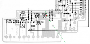
Wire 4 not needed if there is already continuity between those 2 points. Check continuity without wire.
Checked continuity without wire 4 between the two points and there is none. I figured out my multimeter...no audible continuity. So usually on points that have continuity, I will have a digital display of 001 or 000. I got 1 (without any change in numbers) without the wire and 001 with the wire. So the wire is needed I believe.
 
Last edited:

Jboulukos

Member (SA)
Yes the solder pad has tore away from the tract.
Its recoverable but to be honest, we need someone who can solder to a high standard and who can make this good. They would scratch back some of the top surface of that tract and solder to it and glue it in place.
If you feel confident enough, get a better soldering iron.
To solder two wires to one point, twist the ends together and solder as one with plenty of solder.
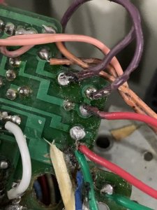
Jump 1 complete, soldered two twisted wires to the tract.

93158BE7-8F94-4FFB-8E4E-25B7927CEA33.jpeg
 
Last edited:

Jboulukos

Member (SA)
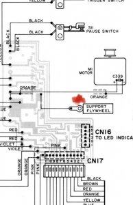
There’s a black wire that is not accounted for that is see from the backside circuit board. I followed it around to the front to the origin and it’s near the lower right front of the cassette deck and attached by a screw. I am wondering if it’s a ground. I’ll attach a photo.
3022CCE9-E57E-4AE5-9D8E-9497C8D5C62D.jpeg
 

Jboulukos

Member (SA)
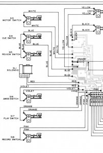
I also found the black wire in the service manual. I’m not certain what “support flywheel” is but at least I know where to solder. 319D92B6-81AD-41E4-AA4E-45D19AD9C98C.jpeg
 

docs

Member (SA)
Or is this the correct jump for #3?
View attachment 49523

yes this is correct for 3. It would be easier with a new capacitor as they come with longer legs.
Looks like you have done everything else. After you have completed the connections across the crack, test all continuity of them and ensure you have connectivity for all of the broken tracts.
 
  • Like
Reactions: Jboulukos

Jboulukos

Member (SA)
yes this is correct for 3. It would be easier with a new capacitor as they come with longer legs.
Looks like you have done everything else. After you have completed the connections across the crack, test all continuity of them and ensure you have connectivity for all of the broken tracts.
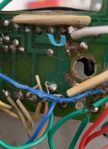
Thanks a bunch for the guidance. I examined the area, front and back for wire 3. I just want to confirm with a photo. Should the wire connect where I put the blue in the photo or does it connect to the point with the white wire, or both?
E95CF834-6BF6-4989-B780-E97B1B636E92.jpeg
 

docs

Member (SA)
Because of the location of the crack I think this is what is needed.
1592494585422.png

So your blue line needs to jump sideways one and connect to where the white one is currently soldered.
 

Jboulukos

Member (SA)
I completed all the jumps and the extra loose wires. Everything has continuity. I put the entire radio back together. I can hear the motor running (Without pushing any buttons) once the power was on. The reels do not spin. Eject works. Record does not engage the wire that will pull the record bar mechanism. Maybe wiring to the motor needs work? I can see other items on the deck that have been attempted to be repaired, poorly.

so far I’ve done the following with the cassette deck:
-replaced all 3 belts
-cleaned components with alcohol and cotton swabs
-repaired the cracked circuit board and replaced/added/re-soldered jump wires and connected other detached wires.

I believe there are other issues mechanically with this deck. For example, in the next photo I have circled the rewind switch mechanism area that has been repaired and looks melted together. D13E76A9-599E-4647-9540-56A5BF29523C.jpeg
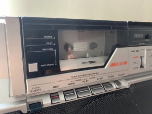
Do the buttons on this model stay depressed when pushed? I believe it’s a different style of deck than the usual. Either way, when play is pressed, the head mechanism does not lift up. I can move the head mechanism upward with my hands when I had the radio opened up.
81C164B3-F75D-4B5E-BFFD-99525F34E5CC.jpeg
I’ve also just noticed some heat coming from the top of the radio. There is a smell coming from the hot area however it’s not a burning smell or smoke smell. I’m not sure if that is from the motor running? I can hear when the motor is running and sometimes I can stop it by spinning the reels. Not sure if the motor randomly comes back on when I’m using the FM radio function. It may because the cassette motor spins in radio function when I first turn it on. I opened the radio to check the hot area. It’s definitely the motor. The cylinder was hot to the touch.
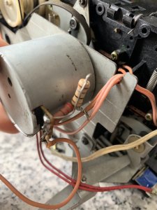
06A9EAD3-4A7E-4299-B802-EB3B78B460D2.jpeg
 
Last edited:

docs

Member (SA)
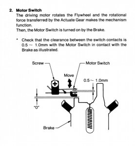
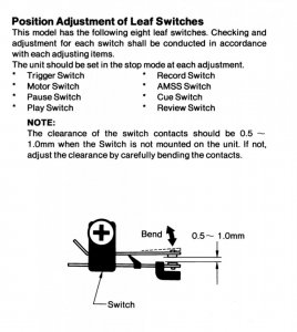
Could be that a leaf switch like the one you showed is constantly engaged causing the motor to run.
You can test leaf switches with a continuity test and enable/disable the switch.
 
  • Like
Reactions: Jboulukos

Jboulukos

Member (SA)
Could be that a leaf switch like the one you showed is constantly engaged causing the motor to run.
You can test leaf switches with a continuity test and enable/disable the switch.
I’m going to open it back up and look at all the leaf switches. It may require that I get into the deck mechanism more so than just from the front face of the deck(there a little cover with two screws) or from the back. I think I will need to disassemble a lot of the deck. There are 8 leaf switches to check. I’m going to check the trigger and motor switches first as they relate directly with the motor operating. Can you give me some direction on where to put the multimeter leads when checking the leaf switches?
I posted a photo previously of the rewind switch that looks melted and reassembled. Even if rewind doesn’t work, I’d be happy with play, stop and maybe fast forward working. Ideally, I’d love if the entire deck worked. I’m hoping there are no missing mechanical parts because it seems like the deck wouldn’t work correctly even if the switches were adjusted to specs. While I open the deck, I’m going to record short video clips of where everything is placed (screws, springs, gears) in order for me to remember how to reassemble.
Is there anything else to do while inside this thing? Should I lube the capstone shaft or the metal push button mechanisms so the metal slides better? Anything else to look into? As always, the assistance is much appreciated.
C8641FB1-AB27-4109-B9B9-4D10B9EB1FA6.jpeg639C725E-EAA0-4455-9875-80387DFE6A84.jpeg4C71BC9C-E310-4A0E-96A7-E8F660EAE444.jpeg
 
Last edited:

Jboulukos

Member (SA)
Update: I turned the flywheel counterclockwise and that seemed to engage a gear. Then play and stop buttons could be depressed moreso. Without power, I manually turned the flywheel counterclockwise pressing play and the head started to rise up slowly and lowered when I pressed stop. Then I attempted to play a cassette with power on. Play worked, raised the head, music heard fine. Stop button did not work so well...needed to push some metal from the lower rear of the deck to get it to disengage the head. Sometimes the stop button works as normal, other times I need to manually press the metal piece that spans the length of the deck from the bottom. FF works great, Rewind works however is slower then faster then slower then faster. Pause and record do not work currently.
This is great.
 

Jboulukos

Member (SA)
Update: record works and pause works however, similar to stop, pause does not always engage. Maybe it needs lube near the metal arm area? The switch seems to be working fine because I can pause and un-pause when the cassette is being unplayed at rest.
 

Jboulukos

Member (SA)
A good lube should sort this out, nice going guys
Thanks RR. Where are the key places to lube? I imagine it would be where metal slides on metal near the buttons and within the deck between the thin metal pieces. Let me know what’s up and I’ll execute the job.
 

Radio raheem

Requiem Æternam
any metal moving parts should be lubed like where the head moves up and down but first you must remove any old grease as this causes more issues going hard over time, i personally have my own way of doing it but it's not recommended so i wont suggest it here to you as it involves wd40 which is a big nono here lol

im sure docs will be along soon to advise you the correct way.... once again im proud you have come this far and have been watching this thread, soldering alone is way beyond me way to go, not sure why there is a line all the way through this message, wtf lol
 
  • Like
Reactions: Jboulukos

Jboulukos

Member (SA)
Thanks RR. You’d be able to solder. Taking time to learn new things is super important and worthwhile. I’m pretty amazed at how this all turned out. When I found the cracked circuit board for the cassette deck, I thought my chances at repairing the deck were significantly lower or completed finished. Then I burned off solder pad and felt horrible. I never want to cause harm to old things. There were moments I thought the work was beyond my understanding. However, I knew that if I didn’t cause harm to the components and kept trying to make the situation better, then I couldn’t lose. And with docs giving me information step by step and addressing all of my questions, I felt better with confidence. I’m amazed that the cassette deck functions seeing what I had to start with. One of the points of the reels is cut up and mangled and was glued. But then when it played I realized that it’s just a cap on the reel and does not participate in spinning. I learned a bunch and will keep going. I’ve been wiping dirt, dust and grease with many cotton swabs.
the deck is still a bit noisy, I didn’t take apart the flywheel or secondary wheels or gears so maybe they are dirty and noisy when they spin. I can always get to that later. It’s fun that it’s never ending, a continuing project. Thanks again to docs and everyone else participating in the forum.
 
  • Like
Reactions: Radio raheem
Status
Not open for further replies.