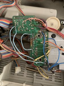
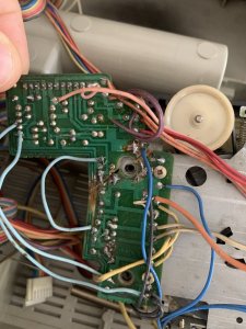
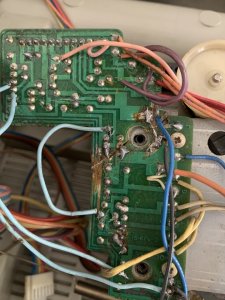
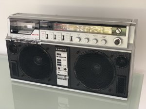
Sanyo m-x650k cassette belts, restoration

Status
Not open for further replies.

Jboulukos

Member (SA)
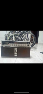
I just purchased an unrestored Sanyo m-x650k and want informational on the size and shape of cassette deck belts for replacement. Also where can I order them. As well as information on resources for completed belt replacement and any other information on restoration such as checking circuits, lubrications of cassette deck components, where to use contact cleaner, cleaning etc...
I want to do right by this machine. Thank you
 

Attachments

  • A1C930B0-F564-448D-8870-1CE448938CCC.png
    A1C930B0-F564-448D-8870-1CE448938CCC.png
    276.1 KB · Views: 14

Jboulukos

Member (SA)
Maybe send member @blu_fuz a PM. I think he still has his M-X650.
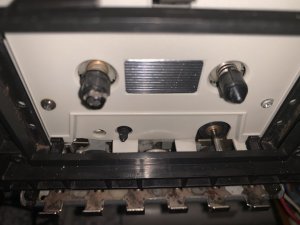
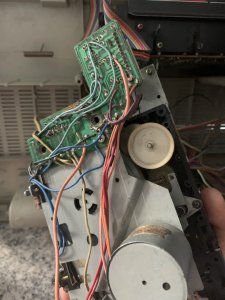
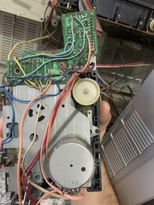
Ok I got the belts and put them on. Upon inspection of the tape deck, I noticed a 2 different screws on the faceplate and the reels look like different sizes with one having adhesive residue on it.

CEB63667-6D1D-4C17-B052-2AACF842B28B.jpeg
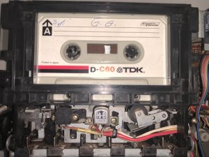
The deck doesn’t move when buttons are pressed and the head doesn’t move upward into the cassette when play is pressed. The pressing of the buttons are not smooth and pressing stop doesn’t always disengage a depressed button.
282D5583-6866-4D8F-AAF4-3F9E0D15933E.jpeg
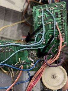
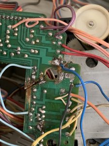
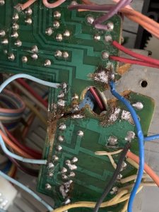
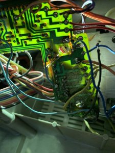
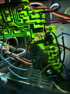
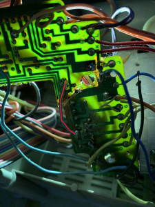
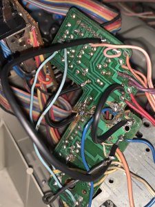
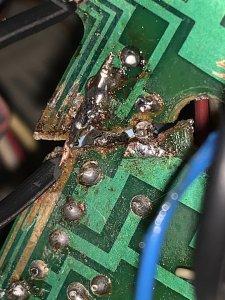
I have seen the motor running quickly in the past without depressing any buttons, just by having the radio on. Also, I noticed the upper portion of the board slightly broken and had been soldered to provide support.
2EDD67B9-0BA1-4DDD-8241-DD8E6F56FD61.jpeg
Not certain where to go from here. I’d like to try to save it but not sure if it’s saveable. Please let me know your opinions on this.
 

docs

Member (SA)
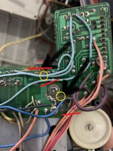
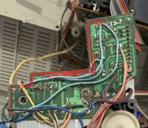
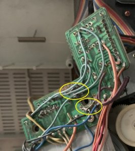
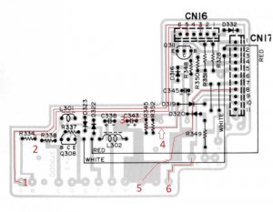
Those light blue wires have been put there to jump the two sides but not on all connections have been jumped in this way for some reason.

It would be a much better job to glue straight down the line of the crack and use matchsticks (red) across the cracks to provide support to both sides. You could put some on the reverse sides too.

I would take a particular look at the areas highlighted yellow.

if in doubt, use a multimeter on continuity test and probe either side of the connections to identify if they are joined or not.

Untitled.jpg
 
Last edited:
  • Like
Reactions: Jboulukos

Jboulukos

Member (SA)
Those light blue wires have been put there to jump the two sides but not on all connections have been jumped in this way for some reason.

It would be a much better job to glue straight down the line of the crack and use matchsticks (red) across the cracks to provide support to both sides. You could put some on the reverse sides too.

I would take a particular look at the areas highlighted yellow.

if in doubt, use a multimeter on continuity test and probe either side of the connections to identify if they are joined or not.

View attachment 49421
Thank you for such great information. It gives me hope. Can I pick your brain some more? The most I’ve done with circuit boards are replacing a potentiometer for a small turntable using a solder sucker and then resoldering. So you can imagine I few questions... the match sticks you are referring to are actual wooden match sticks glued to the board? If so, which glue to use? And which glue on the board crack itself? After the board is more secure, can you explain what to look for on the multimeter to confirm a pair should be linked? I’ve used a multimeter but more so on cars. I still need to learn each time.
 

docs

Member (SA)
Yes just wooden matchsticks glued to the boards to strengthen.
I have used epoxy two part glue to repair boards like this before but they do need some reinforcing, hence the matchsticks idea.
Use epoxy two part across the crack too.
On your multimeter you should see a symbol which is a sound/speaker. here is a random image on the internet https://i1.wp.com/www.electronicsandyou.com/wp-content/uploads/2019/08/Continuity-Symbol.jpg?resize=768,432
Look at the continuity symbol.
When set to this, you can do a test on a piece of wire and it will beep if there is continuity, if there is a break... no beep.

Before gluing anything I would check that all of the connections are made.
 
  • Like
Reactions: Jboulukos

Jboulukos

Member (SA)
Yes just wooden matchsticks glued to the boards to strengthen.
I have used epoxy two part glue to repair boards like this before but they do need some reinforcing, hence the matchsticks idea.
Use epoxy two part across the crack too.
On your multimeter you should see a symbol which is a sound/speaker. here is a random image on the internet https://i1.wp.com/www.electronicsandyou.com/wp-content/uploads/2019/08/Continuity-Symbol.jpg?resize=768,432
Look at the continuity symbol.
When set to this, you can do a test on a piece of wire and it will beep if there is continuity, if there is a break... no beep.

Before gluing anything I would check that all of the connections are made.
awesome, thank you. Also, which size/type of wire should I use to make the connections? How many connections do you see approximately?

7B9608C5-2387-4256-B8BB-5AD7CE49083E.jpeg
I found the epoxy to get at the home center store. Solder for electronics is difficult to find here in Colombia. I have some solder but not certain if it’s the correct percentage of the metals used for this.
Also, what is the best way to separate the cassette deck from the radio and the speakers etc...? When I changed the belts, I was awkwardly suspending the deck keeping it in a certain area not to pull all the other wires connected to it. For this job, I would think it would be best to have it a separate piece to work on, or propped up on some books? Not certain. The circuit board has two screw connections to the back of the deck, however it’s still attached by a bunch of wires leading to the deck and the radio of course. Any thoughts on trying to separate it or just work with it in place? 150A8F09-6774-4423-9515-B17708482522.jpeg

here is the epoxy I will get.0016F035-FBC2-4791-ABA9-3B39B91014DA.png

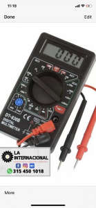
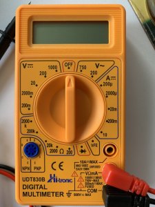
Does this multimeter have the continuity aspect you mentioned? I don’t see the speaker symbol but it may be different in South America.
05067F35-A10C-4E13-A6CD-85D10CD5A331.png
 

docs

Member (SA)
Try turning the entire thing upside down so you can rest the deck on the table.
It is hard to tell from the photos the number of connections across that break.
I would just focus on making sure that you have checked the sections where the previous fix tried to just use solder to jump the connections.
Then by eye, check that you can see all tracts that should be connected cross the break and use your multimeter to test you have continuity.
You could probably just strip some wires from a cord or try use something similar to what is already there.
Here are a few was an example.
Untitled.jpg

Again it is hard to tell but there is something going on around here:
Untitled.jpg

If it is just blobs of solder to connect or bridge over the break in the board, I would remove it all by heating with soldering iron and using solder sucker and ensure you have a solder point on either side, then do the glue work making sure the board is together and attach the wire to connect across afterwards.
 
Last edited:
  • Like
Reactions: Jboulukos

Jboulukos

Member (SA)
Try turning the entire thing upside down so you can rest the deck on the table.
It is hard to tell from the photos the number of connections across that break.
I would just focus on making sure that you have checked the sections where the previous fix tried to just use solder to jump the connections.
Then by eye, check that you can see all tracts that should be connected cross the break and use your multimeter to test you have continuity.
You could probably just strip some wires from a cord or try use something similar to what is already there.
Here are a few was an example.
View attachment 49426

Again it is hard to tell but there is something going on around here:
View attachment 49428

If it is just blobs of solder to connect or bridge over the break in the board, I would remove it all by heating with soldering iron and using solder sucker and ensure you have a solder point on either side, then do the glue work making sure the board is together and attach the wire to connect across afterwards.
Should I try to find solder wick for removal of the solder blobs?
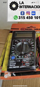
Does this multimeter have what I need?
A362FFE5-4B1B-4086-BCF7-34DEC9818E90.png
 
Last edited:

Jboulukos

Member (SA)
Try turning the entire thing upside down so you can rest the deck on the table.
It is hard to tell from the photos the number of connections across that break.
I would just focus on making sure that you have checked the sections where the previous fix tried to just use solder to jump the connections.
Then by eye, check that you can see all tracts that should be connected cross the break and use your multimeter to test you have continuity.
You could probably just strip some wires from a cord or try use something similar to what is already there.
Here are a few was an example.
View attachment 49426

Again it is hard to tell but there is something going on around here:
View attachment 49428

If it is just blobs of solder to connect or bridge over the break in the board, I would remove it all by heating with soldering iron and using solder sucker and ensure you have a solder point on either side, then do the glue work making sure the board is together and attach the wire to connect across afterwards.
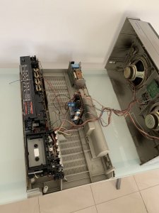
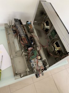
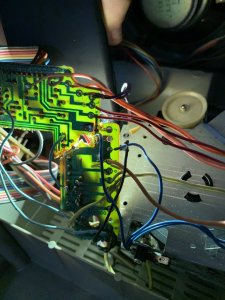
Here is my set up. I took the radio portion and the deck portion off and moved them, flipping the deck slightly.E68E3A28-81AA-4275-9545-C0A3C3FABC41.jpeg2B49A5DD-C61D-4733-9042-E0B71589B91B.jpeg

here is the circuit board crack. I tried to position the wires so their routes can be seen and the crack is visible.
1AD7745D-4C32-453D-87B5-92F3C3868086.jpeg33D086F4-C971-4C62-B34F-61AF62472ADA.jpeg30C02461-6038-4884-A2DC-47DEC4C772CB.jpeg
 

Fatdog

Well-Known Member
Staff member
I suck at soldering, but I think even I could do a better job at jumping traces. One of the previous owners certainly gave it a valiant effort, but wow, what a mess.

I also noticed that one of those maroon colored wires isn't even soldered to anything. Do you know where it is supposed to go?
 
  • Like
Reactions: Jboulukos

Jboulukos

Member (SA)
I suck at soldering, but I think even I could do a better job at jumping traces. One of the previous owners certainly gave it a valiant effort, but wow, what a mess.

I also noticed that one of those maroon colored wires isn't even soldered to anything. Do you know where it is supposed to go?
Right?!! Someone really experimented on this thing. Yes, I just noticed this purple wire as well. Trying to examine it and where it goes. Not certain.
I just located a place downtown that has solder suckers and multimeters. After receiving such great posts here giving great advice and watching some YouTube videos, I feel confident I can clean up the crack and epoxy it for a more secure fix. I’m going to attack it tomorrow once I get the supplies. Hopefully I will be able to fix these electrical issues. I feel there are still mechanical issues with the player even after changing the belts however who knows, maybe it will play with the messed up reel. I bought some sewing machine oil to lube it. I’m also trying to find the Identical cassette deck within other Sanyo or other Japanese models of that same era. Maybe I can find a better quality deck and swap it in there. I’m learning a lot thanks to this forum. Gotta keep pushing to keep this thing alive.33C09505-7E41-4336-867C-98254A913182.jpeg
 

Jboulukos

Member (SA)
I picked up a solder sucker and cleaned up the solder in the crack. I’m going to glue it as well. In cleaning up the sloppy solder, I noticed the crack goes through a hole for an item on the right side (capacitor?) and another wire was removed from the left side solder goop. I’ve started checking the continuity. I should see “001” on the display if there’s continuity, correct? I bought a pretty cheap multimeter and it beeps but I’m not certain it beeps in the continuity setting because it doesn’t have the speaker lines logo. A016BC86-F61D-44F9-AD97-FC209A009A70.jpeg2D7772EE-6A4A-44DD-814E-8A8849399FA6.jpeg3F80AEF0-D6F3-4EB9-ABDD-E2B7DDB07966.jpeg
 

docs

Member (SA)
Im not sure that tester has a beep function.
Just take it slow and get that board secured. Any connections can then be soldered and sorted.
 
  • Like
Reactions: Jboulukos

Jboulukos

Member (SA)
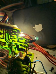
I’m trying to trace these lines so I decided to put a flash light behind the board to see the lines better. Besides the 3 on the far left I think there are 2 more areas that cross the crack. One is marked J on the right on the lower side of the crack. The other looks like it is the 4th line from the left. Any opinions on this? Can the jump wires be soldered directly to the lines on the board or do they have to travel from the beginning part of the line to the end part of the line?

EB91E4D6-1D19-45C0-8949-D45207C3C250.jpeg56DC48DA-64C6-4D44-8EA0-07514655D50F.jpeg0C329B3A-8012-4D9C-ADBD-C34988C08F3D.jpegAF444201-6094-4ABE-9CD4-F396D8CA668F.jpeg
 

Jboulukos

Member (SA)
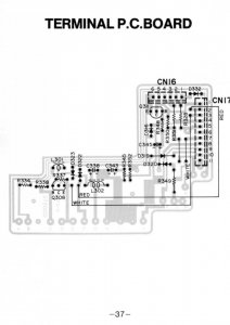
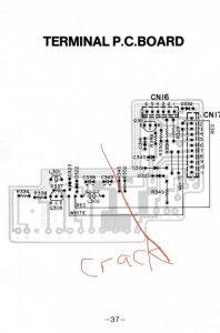
I just found this in the service manual for this model. Looks like 7 lines cross the crack. CA8E273D-A63D-4359-A66C-926326D0D699.jpeg
445396EE-C46E-44B4-80B7-FC8651979E8B.jpeg
 
Last edited:

docs

Member (SA)
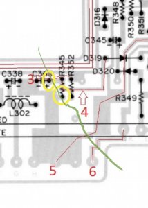
I agree, it looks like there are 6 connections.
Below is where I would connect.

Take care with R345, it might be best to disconnect one side of this as it looks to connect across the crack.

Untitled.jpg

The below wire is a concern to me as it jumps over a few components, I would remove this and move it to the resistor right next to the crack as per number 3 above.

1591887227713.png
 
Last edited:
  • Like
Reactions: Jboulukos

Jboulukos

Member (SA)
I agree, it looks like there are 6 connections.
Below is where I would connect.

Take care with R345, it might be best to disconnect one side of this as it looks to connect across the crack.

View attachment 49482

The below wire is a concern to me as it jumps over a few components, I would remove this and move it to the resistor right next to the crack as per number 3 above.

View attachment 49484
This is wonderful. Thank you as always. I added to the drawing. There are two prongs in the crack, both circled. I feel as though numbers 3 and 4 do not jump the crack following the drawing. They end up both above the crack. The two yellow circles are within the crack, neither on one side or the other. Should I glue the crack and then solder them within their original holes within the crack? ED374AD4-2BDF-48F7-9CB8-C2326E05FC47.jpeg
 

Jboulukos

Member (SA)
I’ve completed 5 and 6, and attempted 3 and 4 although they are both above the crack. I’m using the smallest wire I could find at the electric store. I’m wishing I could find a smaller gauge wire. 1 and 2 were there prior and seem fine when continuity is checked. There are two other extra detached wires, a purple from the top, and a blue that initiated in the original solder blob on the left side of the crack. E1CF4FD4-31F3-4E17-B5F8-2EC634F99AE5.jpeg8216EFF4-1CCE-4B1F-A279-3D59A70321C4.jpeg
 
Status
Not open for further replies.