Sansui cp-f7 deck issue

Status
Not open for further replies.

docs

Member (SA)
Something weird I noticed, while voltage checking at the sensor, if I hold dmm positive lead on pin feeding c28 to q2, play remains engaged until I remove the lead. I also noticed a very small voltage on the ground lead, need to test more around q2 I think.
 

Superduper

Moderator
Staff member
docs said:
Dave, your guess is as good as mine. In a previous post, I already said I can't begin to imagine what the expected signal pattern should be with the OG device since no datasheet exists for it. I also suggested that you check the OG device to see if it's working. I forgot... you even have a scope which should make that an easy test. However, I will say this: the device you chose is not a regular hall sensor. Hall effect sensors return an output proportional to the magnetic field sensed. However, the datasheet for the device you chose identified it as a hall sensor switch. Hall sensor switches operate slightly differently because it also has built in threshold control and works as a switch. Did the magnetic field detected even eclipse the necessary threshold of that device? I don't know. If you scroll slightly further down, you'll see another sensor made by honeywell. If you look at that datasheet, you'll see that this one is NOT a switch.


docs said:
Something weird I noticed, while voltage checking at the sensor, if I hold dmm positive lead on pin feeding c28 to q2, play remains engaged until I remove the lead. I also noticed a very small voltage on the ground lead, need to test more around q2 I think.
So once, again, if you replace the hall effect sensor, you are presuming that it is bad in the first place. If the substitute doesn't work, does that mean that the device chosen wasn't a good substitute, defective? Or was the OG one even bad in the first place? If you perform substitutions and get the result you want, then it's all good. But if you don't check/verify before swapping parts, it often just leads to more questions than answers.

Sm voltage on ground lead... ok. What ground lead? On transistor? Well the emitter goes through a resistor so obviously, there will be voltage drop. On the HES module? Ok, maybe that might be problematic, indicates excessive resistance in the ground lead. Could that be enough to change the threshold detection level to make it function the way the circuit wants? Could C28 be leaky or not sensitive enough to trigger Q2? Maybe change that.. it's cheap enough. Anyway, I suspect you are already investigating that.
 

docs

Member (SA)
Understood, I’m not sure how to test the original sensor, i’ll do some research on that.
 

Superduper

Moderator
Staff member
docs said:
Understood, I’m not sure how to test the original sensor, i’ll do some research on that.
I already tried to explain this to you. The device is simple. It has + and - leads. The 3rd lead is the output lead. Depending on the strength of the magnetic field, it will output a voltage which is directly proportional to the strength of the magnetic field. You can determine which wire is which because you already have the SM which shows the device and the circuitry it is connected to. In the circuit, ground is clearly identified. The + lead can be identified because it's attached to the +5v rail, which leaves the last lead which controls the transistor Q2. Because you have an oscilloscope, put the scope probe on the output lead and hopefully with the magnet turning, you should see a pattern. If you have trouble turning the magnet because you can't get the deck to run, you can simply pull the belt off the reel, loop it over the shaft of an old cassette motor, and run it with a 9v battery. Even without a pulley, the shaft probably spins fast enough to allow the magnet to spin at a pretty good clip. On your scope, set the v/div first to 1v/div and if the signal is too small, drop incrementally until you see a decent pattern.
 

docs

Member (SA)
Firstly, I did a quick test on a test circuit to see if I could see any voltage output as i expected to see a voltage when a magnet came close to the component but this didn't work so I'll put the component back in and get the scope on it tonight to see if I can see a pattern being output.

Struggling with the schematic as parts do not match. For example, q2 in schematic is a 2878 but in my board its a 1815. C27 and C28 are 10uf/16v in schematic but are 10uf/50v in board. There are a few resistors different too.The board looks untouched and original though. In any case, I'll use the ratings in the board but it doesn't make it any easier.
 

Superduper

Moderator
Staff member
Remember that the sensor needs to be powered up in order to function. Also the output might not be as high as you expect. Without a datasheet, we don't know but it could be in the millivolts range and not volts range.

2SC2878 and 2SC1815 have the same power dissipation so they are pretty much compatible, especially if the 1815 is "Y" or "GR" suffix, so I am not surprised if they made this substitution based on product availability. 10uf/50v in this circuit would be absolutely identical electrically as 10uf/16v since it's not gonna see in excess of 16v.
 

docs

Member (SA)
Stumped, tested new and old that much that the small pcb is a mess so Ive created a new one and ordered new pcb prints.
Norm pm’d.
 

docs

Member (SA)
Ok, so there are so many hall sensors of different types like bipolar, unipolar, linear, digital output, analogue output and about 6 other variable options, meaning there are literally hundreds of them.
I purchased a selection of the above options and next to last attempt I’ve found one that works!

If anyone ever has this issue, the replacement hall sensor is:
Honeywell SS495A.

It is a linear ratiometric sensor.

Thanks for all input in particular Norm’s invaluable guidance which I am very grateful for.

The tiny pcb is not designed for numerous messing with and troubleshooting, luckily my lad has recreated a replica which is currently being printed at a cost of £1.52 for 5.
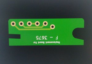
BF7598B2-95CE-41CC-B064-4E804AC5DA20.jpeg
 
Status
Not open for further replies.