RX 5050 - Anyone have a schematic?

Status
Not open for further replies.

caution

Member (SA)
Mar 25, 2014
2,508
344
83
Boomboxery
We're very familiar with that pot. The seven pin pots were used on a lot of boomboxes, it's actually two pots for left and right channel, but one side of each pot have been combined into one pin (for ground), which makes only five pins, then two more pins have been added as taps 40% of the way up on each pot, which go to a booster circuit, so that from 0-40% volume you get extra bass.

Panasonic actually silkscreened the pinouts and circuit diagram on the back of the PCB where they have the volume pot on their DT680, maybe others. Here's the datasheet for it but it's not easy to follow either, so I added some pin numbers and descriptions.


HRmeteohub

Member (SA)
Mar 19, 2017
138
3
18
Croatia
I did not notice when exactly is this difference between channels noticable - with what source of the signal: radio, tape or always?
Just as every body else, I am looking forward for more pictures - dissasembled pot is the next one we expect :)
 

chuckulaa

Member (SA)
Jun 15, 2017
16
0
0
37
Nashville, TN
I did not notice when exactly is this difference between channels noticable - with what source of the signal: radio, tape or always?
No matter where the volume knob is, one channel is weaker than the other. This is true for radio or aux. It is true for Stereo, mono, and stereo ambient.

Sorry for the delay... I was on travel this weekend. Now that it's monday, I had a chance to check on the volume pot again...

We're very familiar with that pot. The seven pin pots were used on a lot of boomboxes, it's actually two pots for left and right channel, but one side of each pot have been combined into one pin (for ground), which makes only five pins, then two more pins have been added as taps 40% of the way up on each pot, which go to a booster circuit, so that from 0-40% volume you get extra bass.

Panasonic actually silkscreened the pinouts and circuit diagram on the back of the PCB where they have the volume pot on their DT680, maybe others. Here's the datasheet for it but it's not easy to follow either, so I added some pin numbers and descriptions.

@caution... Thanks for the volume knob pin out! This has helped me diagnose my problem.

The potentiometer is not working correctly. I removed it from the circuit board and made these measurements:

Pin 1 to 3 = 163k-213k
Pin 1 to 7 = 213k-163k

For the wiper on the other channel

Pin 3 to 5 = 2.7-49.1k
Pin 5 to 6 = 49.1k-3.0

So the channel that uses the wiper on pin 5 seems to behave normal (0-50k ohm), while the channel that uses the wiper on pin 1 seems erroneous (160k-213k). With the higher resistance observed on wiper 1, it would make sense that one channel is loosing volume in the potentiometer.

Will opening up the potentiometer break it? Can I open, clean and repair the potentiometer? Does anyone know where to buy a replacement seven pin potentiometer?
 

caution

Member (SA)
Mar 25, 2014
2,508
344
83
Boomboxery
Yeah with the extra resistance it might just be dirty, might as well open it up for a good cleaning. You can bend the tabs back a couple of times before they weaken and break off.

If that doesn't fix the resistance values and you need a replacement, then I can help you. You can't get these pots anymore. In fact, the 5050 is known as a radio to scavenge these pots from to fix the M90, which uses the same one, but I looked into alternatives not that long ago to replace one of mine and found the same one in a number of 90s-era Panasonics, but with a couple of differences.

First the pins are bent at an angle in order for the back of the case to sit down against the circuit board with the shaft sticking up vertically, which is connected to a motor assembly for remote control. Because of this they have a longer shaft, which needs to be ground down about a quarter inch, and the flat notch on the side of the shaft needs to be extended a bit. It worked like a charm. I've got a few of from thrift store boxes which I've torn apart, so you're welcome to one if need be. You just have to re-use your right-angle mounting bracket, which means prying back the tabs on the replacement pot to attach it.

Here's the thread we were talking about it https://boomboxery.com/forum/index.php/topic/25338-m90-restored-thanks-to-yall-on-boomboxery-jt-chronic
 

chuckulaa

Member (SA)
Jun 15, 2017
16
0
0
37
Nashville, TN
So I cleaned the pot tonight. You can see there is lots of black stuff that came off when I took the cotton swab with some DeoxIt. I even added some fader lube for good measure.

However, my cleaning didn't come with success. The pot is now WORSE! Pin 1-3 now measures 215k - 266k.

It looks like a replacement part is in order...

@caution I quickly looked through your post. I will read it more thoroughly tomorrow. I also did a little research on google today and when I think I stitch it together with your post, we can get something figured out. It's the end of the night tonight!
 

Attachments

chuckulaa

Member (SA)
Jun 15, 2017
16
0
0
37
Nashville, TN
Has anyone had success cleaning these things? It seems that my cleaning last night made it worse! Maybe I need to bend the metal for better contact?

https://www.partsimple.com does have the product number EWCT5AF20B54 listed on their website. However, these potentiometers are on backorder. I don't know how long it would take to get them, or if I would get them!

I am competent to modify the pins and keep the bracket to get these potentiometers working in my stereo.

@caution, I look forward to your advise on the potentiometer issue.
 

caution

Member (SA)
Mar 25, 2014
2,508
344
83
Boomboxery
They won't get them. I already tried. I don't know why I even tried though, most of the parts they list aren't being made anymore. Just a big tease.

If your contacts look okay, you could just re-use that instead of trying to shorten the shaft on the new pot. My pot needed new contacts so I had to.
You just need the part with the carbon tracks, so you can remove that from a pot I send you, and straighten the pins to fit on your board. You might have to jumper the oddball seventh pin, not sure about that one.
 

chuckulaa

Member (SA)
Jun 15, 2017
16
0
0
37
Nashville, TN
I took a couple more pics of the carbon tracks and the contacts.

I also measured the resistance of both carbon tracks. Pin 3-6 and 3-7 both read ~50k. Therefore, the problem is in the connection between the shaft contacts and the carbon tracks. Using fader lube did not fix the problem. The contacts that have a problem are on the larger, outer carbon circle. [i.e. Pin3 (ground) - Pin 1 (left wiper) Pin 7 (left end tap.)]

What a bummer. These 7-pin pots are well documented to have a high failure rate, yet we can't buy any new... :-/
 

Attachments

chuckulaa

Member (SA)
Jun 15, 2017
16
0
0
37
Nashville, TN
@caution sent me a potentiometer that I got in yesterday! To install it, I kept the shaft and contacts of the original pot, and the mounting bracket. I just replaced the wafer with the carbon tracks on it. I had to bend the legs to make it straight, and jumper 'pin 1.' I made the jumper with a resistor leg. Took me about 10 minutes, and the radio is now working!

One weird thing I noticed, capacitor 129 and 229 were different values? One was 0.33uf and the other was 0.22uf. I replaced both with two 0.22uf capacitors. I will be interested to see the schematic so that I can know what value was intended for these positions.

I went ahead and replaced several capacitors with replacements that I have on hand. The radio is now working, but it has a large background hiss, so I'm going to rebuild the power supply as well. I plan to purchase a schematic so that I can replace Q303 (the rusty transistor), replace the diodes from the diode bridge, and replace all of the remaining power supply capacitors. I hope that this will not only remove the hiss, but it will make this radio last a long time.

The RX-5050 sounds alright. It doesn't sound near as good as my '69 pioneer receiver combined with my mid 70s rectilinear speakers, but it sounds pretty decent good. It is very loud, and it is quite a bit brighter. I have found that EQing it by boosting the bass and flat lining the treble gives the best tone. If and when I purchase a schematic, I will post it to this thread, so that someone else won't have to pay for the schematic in the future!
 

chuckulaa

Member (SA)
Jun 15, 2017
16
0
0
37
Nashville, TN
The transistor is an 8.5v voltage regulator and not likely a problem because if it had failed, you would notice much more problems than you are observing and it would be global and not channel specific problem.

Superduper, would you feel comfortable suggesting a modern replacement? I want to rebuild the power supply.

Thanks for all your help, I've been enjoying this boombox all night tonight.
 

caution

Member (SA)
Mar 25, 2014
2,508
344
83
Boomboxery
Glad to hear the pot worked out! Sort of weird seeing someone put a good pot BACK INTO a 5050 :lol:
Not to steal SuperDuper's thunder but I may have an exact replacement for that transistor, what's its number?


By the way, great choice of receiver. I started my musical odyssey on a Pioneer SX-6000 (1971-73) that my father shoehorned into an old Montgomery Ward Airline 2955.
 

Superduper

Member (SA)
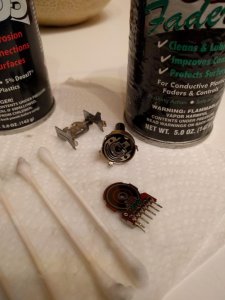
The transistor is 2SC1568. Virtually any TO-126 NPN power transistor will work, recommended 1.0 amp or greater collector current. The application for which this transistor functions is not critical. However, when subbing, always compare the datasheets for the orig as well as the substitute to verify pin out assignments are the same, or adjust accordingly. In most cases, if the assignment is different, it can usually be corrected by reorienting the device 180 degrees as the center pin is "usually" the same. However as I mentioned earlier, why are you selectively replacing components indiscriminately without knowing for sure if there are problems? It's easy enough to check... with unit running, check voltage at B/C/E. If you are getting approximately 9.2/12/8.5, then the transistor is doing it's job perfectly and there's nothing wrong with it. The rusty part is NOT the transistor -- it is merely a heatsink that is clipped to it. If you change the transistor, the heatsink will need to be migrated over and it will still appear rusty. So if the appearance bothers you, then simply remove the heatsink, wire brush it, repaint and replace.

BTW, the original caps that you replaced were the correct value. It is unclear why the engineers set the values differently but it could be due to the fact that the two outputs have slightly different potentials, slight as it is (5.6 vs. 5.7). Besides, they are polyester caps -- they typically don't go bad like electrolytics.

As I mentioned in another thread, the power supply is not usually a source of hiss. PS introduced noise typically manifests as hum since it is 60hz related. Hiss on the other hand is random noise and not of any set frequency. If you want to know for sure, simply power it on batteries and if the hiss is still there, then you'll know that the PS is not the source of the problem. I'm not against rebuilding the power supply. If nothing else, new caps may help stiffen the PS and certainly can be considered preventative maintenance to ensure future issues don't rear it's ugly head. New rectifier diodes? Well, I suppose they are cheap enough but again, throwing parts... why not replace all the semiconductors then? I mean, what's the rationale for replacing these? Anyhow, that's just me -- I like to take a logical approach towards repair.
 

chuckulaa

Member (SA)
Jun 15, 2017
16
0
0
37
Nashville, TN
Cation, I love the pioneer SX receivers. I have a SX-1000td.

Because I ended up getting the RX-5050 for free, I figured it wouldn't hurt if I invested a little in it. Superduper, you build a strong case. I can't argue with a practical, logical approach. I may replace the remaining PS capacitors for preventative maintenance, but I won't pursue replacing the semiconductors.

I'm excited to have this RX-5050. The sound is a bit tinny and thin, but the box does have enough articulation that I can hear all the tracks in a recording. Another bonus: because it is not super valuable, or rare, it will make a nice camping/beach boombox. If it gets a little banged up its not a big deal!

Thanks again guys, I really appreciate it.
 
Status
Not open for further replies.