RX 5050 - Anyone have a schematic?

Status
Not open for further replies.

chuckulaa

Member (SA)
Greetings,

I recently acquired an rx 5050, and the channels aren't balanced. The right channel sounds great, but the left channel is weak. I want to get this bad boy running healthy again, but I can't find access to a schematic.

Does anyone have a schematic for the rx 5050?

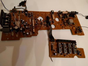
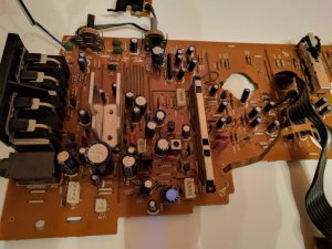
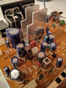
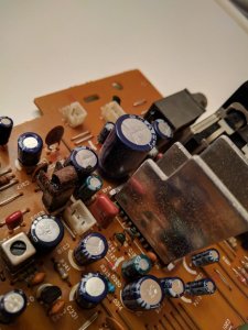
I managed to remove the audio board from the stereo. I can see a suspicious capacitor and transistor.One of the transistors looks like it has seen hell. While I have the board removed I would like to do a recap. This whole process would be a lot easier with a schematic or service maual! I would appreciate any help!

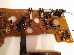
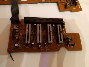
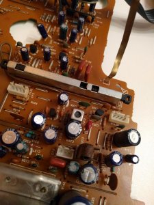
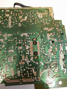
I'll attach some photos of the main board.
 

Attachments

  • IMG_20170615_222110.jpg
    IMG_20170615_222110.jpg
    85.2 KB · Views: 14
  • IMG_20170615_222120.jpg
    IMG_20170615_222120.jpg
    110.8 KB · Views: 18
  • IMG_20170615_222127.jpg
    IMG_20170615_222127.jpg
    86.1 KB · Views: 18
  • IMG_20170615_222141.jpg
    IMG_20170615_222141.jpg
    68.5 KB · Views: 13

HRmeteohub

Member (SA)
Welcome!

I do not have a schema or service manual, but if I also do not see any capacitor (or transistor) in dire need of change. Also, the board looks like it's from 1990's, and generally speaking the capacitors of that age are usually rather stabile/good. Therefore, I would sugges not to change capacitors.
Just one thing. The potentiometers do look a bit dirty. Did you performe the cleaning/degreasing? Also, I would suggest thorough inspection of pots first, as there is no obvious faulty cap or tranzistor on the images. Even showing the position of such failed parts can tell about the reasons of failure and direct how to repair it - in a way.

So, please give us a story - how it went bust, and what happend since. Please.
 

chuckulaa

Member (SA)
So my post was bad last night. It was late and I was tired.

First, I'm excited to be joining this forum! I just bought this 5050 and its my first boombox. I love muisc gear, and when I can find time, I fix up old audio equipment that needs a little TLC.

As mentioned, the left channel is weak, maybe a little distorted. It has sound but it doesn't sound as loud or good as the right channel.

I have cleaned the two potentiometers with dexoit and fader lube. It did not fix the stereo imbalance problem.

Now, I took a photo of the suspect transistor, Q 303. The capacitor looks burnt, but it might be from the heat of the Q 303. I suspect it might need to be replaced.

A schematic would really help me identify what all the individual components are doing.


I don't know how the left channel busted, I just bought this unit, and it came with the left channel a little weak. (although the seller claims this is a 'new' problem.)

Here are a couple photos of the suspect transistor, Q303.


I retouched the solder joints with my soldering iron, but it still did not fix the problem. There must be a blown transistor somewhere on the left channel, right?
 

Attachments

  • IMG_20170616_084323.jpg
    IMG_20170616_084323.jpg
    118.4 KB · Views: 25
  • IMG_20170616_084336.jpg
    IMG_20170616_084336.jpg
    96.5 KB · Views: 10
  • IMG_20170616_084404.jpg
    IMG_20170616_084404.jpg
    110.6 KB · Views: 14
  • IMG_20170616_145925.jpg
    IMG_20170616_145925.jpg
    162.8 KB · Views: 18

HRmeteohub

Member (SA)
hm....

Q303 looks a bit rusty, If you remove the metal part from it, I bet you are going to see that it is a power type, not a signal one. My gut tells me it is PNP, 30V, 3-5A, 20W or similar. It looks like there is via from the collector of the Q303 to CP4, a connector for some part of mechanism. It could be used for turning the power to some part of the tape deck (relay, solenoid or motor), and it is probably OK. Let me explain why the transistor is not likely culprit. This is stereo equipment, meaning that all parts should be doubled, symmetrical - one for left one for right channel. There is only one Q303, and connected to mentioned socket with label MECHA(nism?). But, hey, test it if you want to.

Did you deox the slider rec switch (on the board)? Please check and clean the headphone jack, as it can also produce problems.

Also, it looks like this amp does not use bridge configuration, meaning that 1000uF/10V capacitors (one for left, one for right channel) are used to separate speakers from offset voltage on the amp (chip under the sink) output. Since C132 does have some smidge on it, as visible on images, test it, replace it, and if it does not make a difference, put it back. Capacitor C132 is sitting right next to Q303. Hopefully it is for left channel. If you can not measure it, use/put new one instead (1000uF/16V is also fine) and try if this removes the distortion.

By the way, nice photos!
 

baddboybill

Boomus Fidelis
1st thing you should try is cleaning switches with deoxit or similar and work switches 20-30 times. Also check with headphones to see if problem persists. Maybe the headphone jack needs cleaning
 

Superduper

Moderator
Staff member
The transistor is an 8.5v voltage regulator and not likely a problem because if it had failed, you would notice much more problems than you are observing and it would be global and not channel specific problem. The capacitor is for the output and likely the source of your problem. If you change it, also change the complementary one for the other channel or else you may notice unbalanced sound. Capacitors of different brand, age, and type can have different sonic characteristics that could be noticeable.

You can buy the service manual (with color schematic) here:
https://www.analogalley.com/osccart/product_info.php?products_id=2178
 

HRmeteohub

Member (SA)
Listen to the SuperDuper - sounds like he/she saw the schema, and knows the stuff. Also, as bafboybill said: clean the switches, connectors!

Nevertheless, the board clearly says Q303, not IC303, and underside says "B C E" (shot for emitter, collector, base), leading me to believe that is a transistor, and not voltage regulator IC.

I second changing capacitors for both channels. I always change them for both ch. However, if that does not help, that would be nice challenge! It would not hurt to test the amp with some outside signal source.
 

Superduper

Moderator
Staff member
HRmeteohub said:
Nevertheless, the board clearly says Q303, not IC303, and underside says "B C E" (shot for emitter, collector, base), leading me to believe that is a transistor, and not voltage regulator IC.
Read my post again & you'll see I said that the "transistor" is a voltage regulator. I did not mention IC. Transistors are extremely versatile components & can do many things, voltage regulation among them. Most regulators of the boombox era were designed using discrete zener diode/transistor combinations as IC regulators did not really manifest until later. If you look at the internal block diagrams of the 7805 IC regulator, you'll notice that internally, there are..... yep, zener diodes & transistors.
 

chuckulaa

Member (SA)
Okay. I did a couple of tests to rule out that capacitor. First, I removed it, tested it with my fluke. It tested almost right at 1000uf. I also tried two separate 1000uf capacitors rated at 16V that I have on hand. It did not fix the problem. I switched the two capacitors, and the problem persisted.

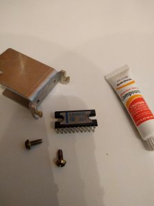
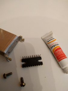
I also tried giving the switches another good clean. I cleaned the tape Rec switch, the power/mode switch, the radio switch, the tape switch, and the stereo switch. I don't know what to do next, so I removed the IC 304 to have a look at it. I was interested in it because half of it looked like it was running hotter than the other half (from the bottom of the board.) I took it out, and it looks fine I think, but I don't know how to test it.

I took some photos of it while I had it out. IC 304 is a LC4500 3B1. I don't know what the brand is.

I guess some small semiconductor company that got bought out by one of the big dogs in the 80s.

Any votes what to try next?
 

Attachments

  • IMG_20170617_130158.jpg
    IMG_20170617_130158.jpg
    43.9 KB · Views: 8
  • IMG_20170617_130213.jpg
    IMG_20170617_130213.jpg
    44.1 KB · Views: 27

chuckulaa

Member (SA)
Would it be worth replacing? Seems to be a ~$10 part. Are there any modern equivalents?

Thanks for your input guys! I am hoping to make this an informative post for future 5050 owners!
 

Superduper

Moderator
Staff member
Amp chip modules are almost always part specific and there are no generic configuration or pin-out standards. Additionally the modules always require an accompaniment of external supporting components. Bottom line is that without other circuit changes, you cannot simply drop in another module, you must change with the correct part number. The exception is semiconductors designed to be part & pin compatible such as with NTE components.
 

HRmeteohub

Member (SA)
Perhaps it would be useful to test what kind o signal comes in to the amp, before you buy new chip. It is not unheard of that the one channel goes bad, but there are other parts around that could make it look bad. Test everything (trace signal with another amp, inject signal from another source, etc.) in audio path before amp and then test other components around this audio amp chip. Could it be just speaker problem or the audio is bad also on headphones?
I believe now the comes the time when the schematic gets useful.

No disrespect intended @SupreDuper, sorry, my mistake.
 

chuckulaa

Member (SA)
The problem is in the signal path. One of the first things I did was switch the speaker channels to see if the problem switched sides. It didn't. I also checked with headphones it did not circumvent the problem.

Tonight, I checked all of the electrolytic capacitors in the stereo signal path. They all checked fine. I went ahead and replaced all of the capacitors that were 1uf and smaller with metal film capacitors.

The problem is still there. I'm going to order a replacement LA4500 off eBay. I'll let everyone know if that fixes the problem.
 

Superduper

Moderator
Staff member
chuckulaa said:
Okay. I did a couple of tests to rule out that capacitor. First, I removed it, tested it with my fluke. It tested almost right at 1000uf. I also tried two separate 1000uf capacitors rated at 16V that I have on hand. It did not fix the problem. I switched the two capacitors, and the problem persisted.
If you swapped the L/R output capacitors and it made no difference, then the problem that you are having probably isn't the capacitor, although if it has leakage, I would change them anyway. Something happened to it whether it was scorched or rusted or leaked, I wouldn't reinstall in that condition. It's cheap enough. That being said, you keep mentioning that you "checked" the capacitors, however a capacitance test is only one thing that goes bad on a cap. There are other problems too which are even more important which is leakage and ESR. Not sure if your fluke can measure those but I think not. You will probably want to get an LCR meter for that, although in practical sense, it's far easier and simpler to just change caps.


HRmeteohub said:
No disrespect intended @SupreDuper, sorry, my mistake.
@HRmeteohub: None taken -- I just wanted to clarify why I stated transistor and not IC, quite simply because that is in fact a power transistor and it's function is most definitely voltage regulation. The rusty portion is nothing to do with the transistor -- it's the clamp on heat sink.


chuckulaa said:
The problem is in the signal path. One of the first things I did was switch the speaker channels to see if the problem switched sides. It didn't. I also checked with headphones it did not circumvent the problem.

Tonight, I checked all of the electrolytic capacitors in the stereo signal path. They all checked fine. I went ahead and replaced all of the capacitors that were 1uf and smaller with metal film capacitors.

The problem is still there. I'm going to order a replacement LA4500 off eBay. I'll let everyone know if that fixes the problem.
Again, with the capacitors, check ESR and leakage, not capacitance but you already changed them so hopefully they are out of the equation. As for the amp chip, it may indeed be bad, as amp chips do go bad frequently enough and in the beginning, it does seem like they start out distorting as they fail. However, the simplest thing to have done in the first place instead of continuing to just throw parts at the boombox and hope something fixes it, would have been to take a logical approach AND START WITH A SCHEMATIC DIAGRAM. At this point, if I were you, I would desolder the L signal input pin of the amp IC to divorce it from circuit, then short the L/R input pins to bring the (clean) right signal to the L side as well and see if you now get clean audio out of amp. IF you are certain that the headphone jack and EXT speaker jacks are both clean and passing good signals, then you can reasonably conclude that:

IF issue fixed, then AMP chip is not the source of the problem and the issue lies before the amp chip.
IF the issue persists, then the AMP chip is probably bad.

On the other hand, this approach does require the schematic so you might as well just try a new amp chip and see if the problem is fixed.
 

chuckulaa

Member (SA)
That being said, you keep mentioning that you "checked" the capacitors, however a capacitance test is only one thing that goes bad on a cap. There are other problems too which are even more important which is leakage and ESR.
This is a good point. I have been able to test the capacitance of these capacitors. I don't have the capabilities to test the ESR and leakage. I plan to replace all of the large electrolytic capacitors around the power chip, and I have purchased nichicon replacement.

Furthermore, there are lots of places to improve this circuit for better hifi characteristics. I have already replaced twelve 1uf, two 0.22uf, two 0.1uf, two 0.47 uf electrolytic capcitors with metal foil capacitors.

I haven't bought the schematic yet, because it think it should be free and not $12. If I end up buying the service manual, I will post the schematic on this forum.

Furthermore, I found two LA4500 power amp ic for $9.95 of eBay. I do not mind investing a little bit of money in this unit, as I got this boombox for free. Hope the amplifier fixes the problem.

Thanks for your help.
 

caution

Member (SA)
There are dual channel 5.3W amps available but not in DIP 20. Doesn't look like a drop-in equivalent was ever made.
Some of them might be functionally compatible, but it would be quite a hack hooking it up.

By the way 3B1 just means it was made in 1983, second month, first week.
 

chuckulaa

Member (SA)
You know maybe the volume or balance pot is not working properly. I highly doubt amp chip is bad
I have cleaned both potentiometers several times with DeOxit.

Shouldn't that clear up any problems with a potentiometer?

I got a new power amp chip in the mail today. I will install it tonight and see if that helps. If it doesn't work then perhaps I will consider replacing the potentiometers.
 

chuckulaa

Member (SA)
I replaced the LA4500 power amp ic. This did not fix the problem.

Tonight, I cleaned all of the potentiometers DeoxIT. I also cleaned the headphone jack very thoroughly. I have cleaned everything with DeoxIT 3-4 times. This did not fix the problem.

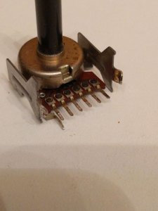
I desoldered the volume and balance potentiometer, and cleaned them. I measured the potentials on the balance, and they were equal to both sides. I did not measure the potentials on the volume potentiometer, because I have never seen a potentiometer with 7 outputs!

The back of the potentiometer reads "50kΩB 32N(A)."

Does anyone have experience with these potentiometers? What is the pinout? Are they reliable?

I'm out of ideas to test with this circuit. Should I buy the schematic? Does anyone else have any ideas?

Charles
 

Attachments

  • IMG_20170622_1821031.jpg
    IMG_20170622_1821031.jpg
    54.8 KB · Views: 13
Status
Not open for further replies.