Repair and modding of Sony DoDeCaHorn CFD-900

Status
Not open for further replies.

yammi99

Member (SA)
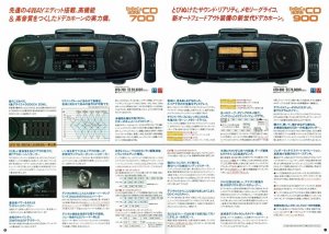
Sony’s boombox series from the 80ies with a special technology for bass improvement had the strange name “DoDeCaHorn” and is probably not well known outside of Japan.

The top of the line models were CFD-700 and CFD-900. The 700 has a 5-band equalizer with mechanical sliders and a mechanical switch to change the functions to Tape, Radio, CD, AUX, that could not be operated with remote control.

On the 900 all is electronically controlled and can be operated with RC.
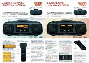
CFD-700 vs. CFD-900 a.jpgCFD-700 vs. CFD-900 b.jpg

I started with the CFD-700 that is often available on Japan’s Yahoo auctions. I could repair it as good as possible. After that I was thinking, that I need the more sophisticated CFD-900.

At the end I had to order two devices to make one almost fully working. Those boomboxes are fully crowded with electronics and have a lot of IC’s inside. If there is something wrong, it will be difficult to repair. But luckily most problems are just related to mechanics, especially on the tape decks.

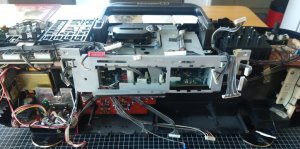
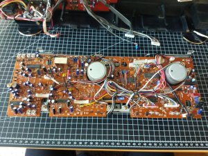
So I found out, that Sony here used some kind of grease that hardened over the time. The tape mechanism then was not movable anymore. I cleaned it with iso and used some oil to loosen everything. The tape mechanisms are not easy accessible, as on the back side is attached the pre-amp board with a lot of wires. I made a lot of pictures to bring it back to initial state. Of course also all 4 belts had to be replaced.

During my work on this device I added some additional features:

  • As the radio has only the Japanese FM frequency range from 76…90MHz, I built in an FM converter that shifts frequency for 10MHz and 20MHz. Now I can listen to German FM radio.
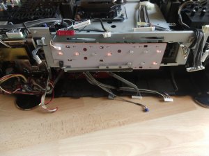
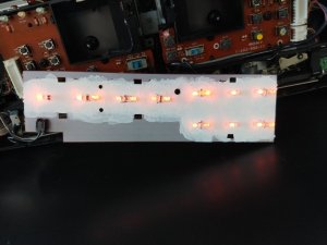
  • The display is illuminated with incandescent bulbs and lights up only when attached to AC Mains. As on one display some bulbs were burned, I changed it to orange LED’s and connected them to another point on PCB, so that they work now also in battery mode.
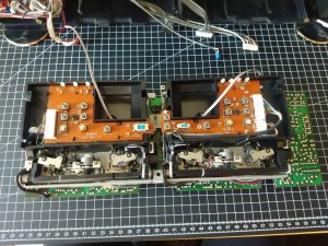
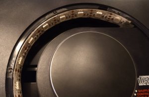
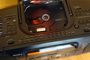
  • Furthermore I added LED’s to tape decks and the CD-Player. On CD player it is possible to change the color as there are RGB LED’s.

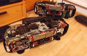
On the next pictures are some impressions of the repair process.
12.jpg

Some bulbs are burned
15.jpg
13.jpg

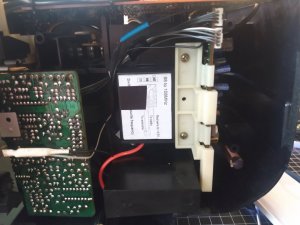
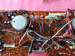
Pre-amp board on back side of tape decks
16.jpg

Tape decks during adding LED's
17.jpg

New LED's, painted the board with white color to make it brighter
20.jpg

FM Converter
14.jpg

RGB LED stripe in CD-Player
18.jpg

Controller for RGB LED's
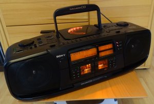
08.jpg

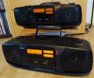
The final result
02.jpg

Here a comparison of Display with bulbs (front) and display with LED’s (back).
10.jpg

Small video, showing the functions after repair:
CFD-900 Functions
 

goodman

Member (SA)
Congrats for this upgrade.
Your Sony looks so shine now.
This is very complicated device.
That was the golden age of electronics products.
Today most companies made only TV's and smartphones...
This is so sad...
 

yammi99

Member (SA)
Great Job Bro !!! How's the sound of the newer DoDeCAHorns ?

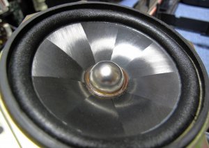
Those devices have a special speaker design. The cones are made of Carbon and the caps made of Titanium. Alltough they have only 7W power, together with the woofer they deliver a warm sound with strong but not punchy bass.
23.jpg

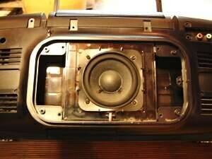
By the way, as the urethan edges of the original woofer were broken, I replaced it with a Visaton FR 8 JS.
22.jpg

Visaton speaker

This is a full-range speaker, but it goes down to 80Hz and the boombox directs only the lower frequencies to the woofer.
 
  • Like
Reactions: allan1836

allan1836

Member (SA)
Those devices have a special speaker design. The cones are made of Carbon and the caps made of Titanium. Alltough they have only 7W power, together with the woofer they deliver a warm sound with strong but not punchy bass.
View attachment 51028

By the way, as the urethan edges of the original woofer were broken, I replaced it with a Visaton FR 8 JS.
View attachment 51029

Visaton speaker

This is a full-range speaker, but it goes down to 80Hz and the boombox directs only the lower frequencies to the woofer.
If I were you I will just buy replacement foam surrounds edge for the original Sony woofers. It looks mean with exotic parts. DIY replacement is easy just follow demo videos in youtube. I've done several surround edge replacements myself.
 

yammi99

Member (SA)
The speaker is already at a friend of mine. He will replace the edges of the original woofer. :-D
 

Timecop1987

Member (SA)
great boombox - great job on customizing it! I do have a soft spot for these DoDeCaHorns - I own a CFD-DW95 MK V and might aswell add a CFD-900's to the collection after seeing yours 8-)
 

hopey

Member (SA)
Just imagine what it would cost to manufacturer this beast today $$$

Hats off to you for managing to put it back together. have you ever worked on the Sharp Twin Auto Reverse Boxes?
 

yammi99

Member (SA)
Hats off to you for managing to put it back together. have you ever worked on the Sharp Twin Auto Reverse Boxes?

Not yet. I have a SHARP QT-Z6 in my cellar, which needs much effort to repair. Seems to be difficult?
 

hopey

Member (SA)
I have managed to re-belt the mech with minimal disassembly, but now i have multitude of connections and wires that cross from one side to all the way to the other side of the box.
 

Timecop1987

Member (SA)
After reading your post and seeing the video i went ahead and bought myself a CFD-900. Looking quite flawless but one tapedeck not working and the subwoofer also needs to be refoamed/replaced. Other than that: What a great piece of machinery this is!

Where did you get the FM converter? did you solder anything to connect it?

I would be happy to hear from you - we also could exchange PM's in german, this way i may get a better understanding :-)
 

yammi99

Member (SA)
Hi,

you will get a PM.

FM Converter:
On ebay

Here are already some pictures.

FM Converter, + pole on tape deck PCB (12V):
FM Converter Connection.jpg

Tapedeck LED:
Tapedeck LED.jpg

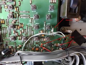
Display and CD LED (5V each):
Display - CD LED.jpg
 

salmansh8

New Member
Sony CFD-900 was an Amazing product with the capital "A".
I'm surprised it even has a high speed CD to Tape dubbing feature, something which I never saw before even in so many expensive Mini Hi-Fi's over the past 25+ years, Sony, Aiwa, Panasonic, JVC etc.
I'm originally a Mini Hi-Fi enthusiastic but Sony CFD-900 made me slip into develop interest on boomboxes now. I ordered one from Japan auction sites and I was able to make the cassette tape works, what now I need is the Remote Control and the guidance to setup lcd backlit to make it work even in battery mode.
Any help will be appreciated.
Thanks.
 

dubout

Member (SA)
Those devices have a special speaker design. The cones are made of Carbon and the caps made of Titanium. Alltough they have only 7W power, together with the woofer they deliver a warm sound with strong but not punchy bass.
View attachment 51028
Maybe the speaker design was what gave the box it's strange name. Far fetched, I know, with a dodecahedron having 12 sides (not 9) and being a sphere, but still ...

What an amount of work, knowledge and detail you put in these boxes is just amazing. Fantastic job!
 

yammi99

Member (SA)
Sony CFD-900 was an Amazing product with the capital "A".
I'm surprised it even has a high speed CD to Tape dubbing feature, something which I never saw before even in so many expensive Mini Hi-Fi's over the past 25+ years, Sony, Aiwa, Panasonic, JVC etc.
I'm originally a Mini Hi-Fi enthusiastic but Sony CFD-900 made me slip into develop interest on boomboxes now. I ordered one from Japan auction sites and I was able to make the cassette tape works, what now I need is the Remote Control and the guidance to setup lcd backlit to make it work even in battery mode.
Any help will be appreciated.
Thanks.
Hi salmansh8,

welcome to Boomboxery. Finally you found the link :-D

The LED mod is not that difficult, but you need some electric knowledge and soldering skills. Originally in display there are small incandescent bulbs. They take to much power to be operated in battery mode. Therefore I removed all from the PCB and replaced them by 3mm orange LED's. On backside of PCB I modified the conductive paths so, that all LED's are connected in parallel. You need to cut some paths and connect some. Finally you need a pre-resistor in series to all the LED's.
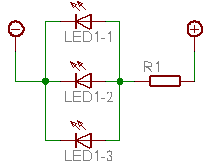
Would be at the end such a circuit (example with 3 LED's in parallel):
par_glob.gif.pagespeed.ce.VyYQLrtO3q.gif

The value of the pre-resistor depends on supply voltage, LED parameters and number of LED's.
I searched on the SONY mainboard a point were I have a permanent voltage in POWER ON state and no voltage in POWER OFF state, all in battery mode. You see this point on my last foto above ("Display LED"). In this case it is 5V. Furthermore you need a GROUND point (- Pole). You find it also on the foto.
To these points I connected the 2-wire cable that is attached to the display light PCB.

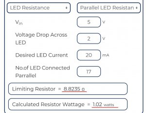
I used in total 17 LED's, because with LED's the light was not so equal as with original bulbs.
For calculation of pre-rsistor you find an example here:
LED in parallel - calculator
LED resistor.jpg


I hope, this explanation helps a little bit.

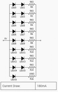
If you don't want to connect all LED's in parallel, you could built it for example also like this:
LED solution 2.JPG
 
  • Like
Reactions: AE_Stereo and hopey
Status
Not open for further replies.