So a few months back I tinkered with the Bluetooth modules our good member blu_fuz put us onto in this thread:
https://boomboxery.com/forum/index.php/topic/23129-m70-m90-with-hardwired-bluetooth-module-mod/
I got a couple myself, played with them on a trc-931 for a while to see how they work, different ideas to install, but never completed an install.
So last week I finally decided to buck up and finally complete an install, but on my Trc-920 instead. Here goes...
I wanted to run this off of a switch in line with the power switch, so it would only worked when the box was powered on, but also switchable on its own, so it wasn't always on with the box.
And since these are meant to run off 12v, I noticed although this is considered a 12v radio, it actually runs at 14v when plugged into the wall. So I also wanted to install a 12v regulator to make sure the module doesn't burn up, as previous tests burnt up a couple modules at 15v.
Here's a couple pics, I'll explain a little more along with them.

This is the module with the 12v regulator connected to it. I cut the RCA ends off, so I could solder the positives to the audio inputs on the box.

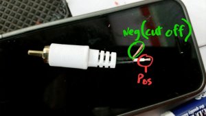
This is how the RCA cable is, basically the negative is around the positive audio wire. I uncovered it back and cut the neg so I could be sure they didn't short out.

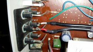
Here is the left and right (red/white) positives soldered to the input posts. As you can see I put heat shrink around where I cut back the RCA cables.

This is where I installed my switch. The wire storage has this expanded area, big enough to reach my finger in. It's hidden completely from the outside, all I have to do is pop the battery door off real quick and flick the switch. We'll see if that was a good idea or a hassle later. But it has the wire coming from the radio power switch, the from this switch to the module, via the 12v regulator.
Now with the problem I had. This module shares the same power ground with the audio ground it seems. Probably typical, I have no clue. So with me testing before, I found if I ground the module, AND use the L&R audio negatives, it has a high pitch sound. Which is why I cut the audio negative, I was just going to use the module's ground. So I soldered it to the negative audio input side. Well that made a terrible ticking noise, even with the volume all the way off, the speakers ticked. Weird. Then I played around for a couple hours a day, thinking it had to be a power issue.
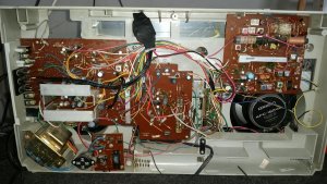
Long story slightly shorter, DON'T use the audio negative as a ground!!! I found the best place to ground this module is the main ground on the box. Now it's crystal clear. Since this module uses the same ground with the audio, I think it was sending a power signal through the speakers??? I don't know, just my guess. Here some pics of where the correct ground for this module should be on a 920.

And here's the module completely wired in, zip tied up to look, well, as nice as a Lasonic wire nest can look.
Not sure what else to say... I love it. Tested it for about 5 hours today, crystal clear. Works great. Any questions or comments please bring them on.
https://boomboxery.com/forum/index.php/topic/23129-m70-m90-with-hardwired-bluetooth-module-mod/
I got a couple myself, played with them on a trc-931 for a while to see how they work, different ideas to install, but never completed an install.
So last week I finally decided to buck up and finally complete an install, but on my Trc-920 instead. Here goes...
I wanted to run this off of a switch in line with the power switch, so it would only worked when the box was powered on, but also switchable on its own, so it wasn't always on with the box.
And since these are meant to run off 12v, I noticed although this is considered a 12v radio, it actually runs at 14v when plugged into the wall. So I also wanted to install a 12v regulator to make sure the module doesn't burn up, as previous tests burnt up a couple modules at 15v.
Here's a couple pics, I'll explain a little more along with them.

This is the module with the 12v regulator connected to it. I cut the RCA ends off, so I could solder the positives to the audio inputs on the box.

This is how the RCA cable is, basically the negative is around the positive audio wire. I uncovered it back and cut the neg so I could be sure they didn't short out.

Here is the left and right (red/white) positives soldered to the input posts. As you can see I put heat shrink around where I cut back the RCA cables.

This is where I installed my switch. The wire storage has this expanded area, big enough to reach my finger in. It's hidden completely from the outside, all I have to do is pop the battery door off real quick and flick the switch. We'll see if that was a good idea or a hassle later. But it has the wire coming from the radio power switch, the from this switch to the module, via the 12v regulator.
Now with the problem I had. This module shares the same power ground with the audio ground it seems. Probably typical, I have no clue. So with me testing before, I found if I ground the module, AND use the L&R audio negatives, it has a high pitch sound. Which is why I cut the audio negative, I was just going to use the module's ground. So I soldered it to the negative audio input side. Well that made a terrible ticking noise, even with the volume all the way off, the speakers ticked. Weird. Then I played around for a couple hours a day, thinking it had to be a power issue.
Long story slightly shorter, DON'T use the audio negative as a ground!!! I found the best place to ground this module is the main ground on the box. Now it's crystal clear. Since this module uses the same ground with the audio, I think it was sending a power signal through the speakers??? I don't know, just my guess. Here some pics of where the correct ground for this module should be on a 920.


And here's the module completely wired in, zip tied up to look, well, as nice as a Lasonic wire nest can look.

Not sure what else to say... I love it. Tested it for about 5 hours today, crystal clear. Works great. Any questions or comments please bring them on.


 those Kenwood speakers must pound?


