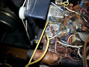
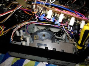
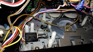
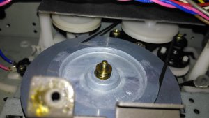
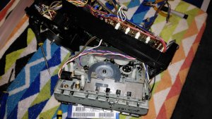
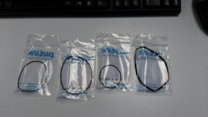
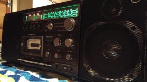
I ripped into this thing last night and now I've got the chassis totally removed from the shell. Its a complex beast for sure. I'm not sure at this point how to access the belts in the best way to avoid complications so I will be looking at this more closely now I can see around it better.
My Sanyo M9998K
- Thread starter markoneswift
- Start date
- Status
- Not open for further replies.
I certainly think that chassis removal is the way to go, before unscrewing ANY circuit boards. The engineers who assembled these must have had some method to their madness, I just need to figure out what it is !
T-STER
Member (SA)
I have been promising to put something together on the rebelt of these but i just cannot catch a break on time at the moment, swamped with work.
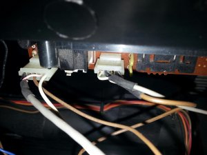
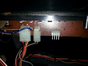
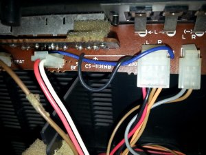
Here are the pics i took of mine so i had a record of wire locations, may be useful:
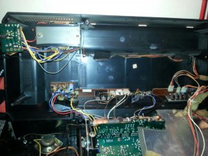
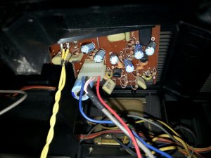
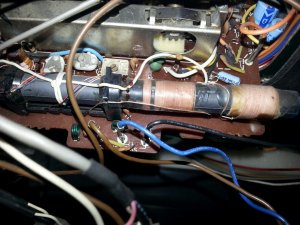
The chassis as you mentioned needs to be removed from the case, this bit is reasonably easy with 5 screws around the edge, they are highlighted in the service manual.
Once removed you can loosen the deck from the front, this gives enough slack later to access the belts from the rear.
The white wires shown in the next pic have to be disconnected from the board on the rear. Be aware this rear board is attached to the main board by pins and need to be lined up carefully and pushed together on reassembly.
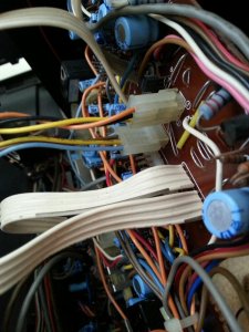
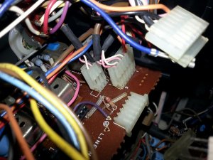
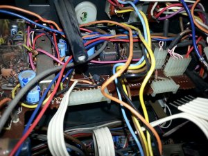
There are various wires around the edges of the rear board that need to be loosened from their wraps to give enough slack to lift the rear board. It will not lift up completely out of the way but enough to prop it up and get at the plate over the flywheel. Getting the belts on is tricky as there is limited space but i used dentistry tools with little hooks on the end and it was ok.
The board doesn't lift high enough either to get a big screwdriver in so i used a right angled driver as the screw isn't particularly tight.
Thats all i remember offhand but i am going to try and find time to get the back off this weekend and get some more pics for a more definitive guide.
Here are the pics i took of mine so i had a record of wire locations, may be useful:


The chassis as you mentioned needs to be removed from the case, this bit is reasonably easy with 5 screws around the edge, they are highlighted in the service manual.
Once removed you can loosen the deck from the front, this gives enough slack later to access the belts from the rear.
The white wires shown in the next pic have to be disconnected from the board on the rear. Be aware this rear board is attached to the main board by pins and need to be lined up carefully and pushed together on reassembly.


There are various wires around the edges of the rear board that need to be loosened from their wraps to give enough slack to lift the rear board. It will not lift up completely out of the way but enough to prop it up and get at the plate over the flywheel. Getting the belts on is tricky as there is limited space but i used dentistry tools with little hooks on the end and it was ok.
The board doesn't lift high enough either to get a big screwdriver in so i used a right angled driver as the screw isn't particularly tight.
Thats all i remember offhand but i am going to try and find time to get the back off this weekend and get some more pics for a more definitive guide.
Attachments
I'm at the capstans now and the belts weren't too but had somehow got all twisted together. I can try to get belts on but I'm not too hopeful that any of this will ever work again ! They say fortune favours the brave though.....
Attachments
Key points so far, remove the chassis, disconnect rear cover and front cover completely (no desoldering required, all screws). Access to flywheel cover is very tight, two tiny little screws need removing from the bottom of the piano key control board to allow a bit more access to the belt area.
Oh boy.
I've ordered the belts today, so more updates to come once they arrive. I don't suppose you've got an idea of which belts go where have you ? I've ordered 4 in total, based on the listing at Turntableneedles.com. I'm a bit confused as to which square belt goes where though because there are two or three of similar lengths. The only really obvious one is the flat drive belt !!
Any help would be much appreciated ! Cheers.
Hey thanks T-Ster for posting those. I'd actually just started getting into mine when you posted so hadn't seen your pics. My experience matches yours so far, although I wonder about those white wires which you mention about disconnecting from the back. I haven't touched those and I seem to have been able to persuade everything up far enough to get access to the belt area.T-STER said:I have been promising to put something together on the rebelt of these but i just cannot catch a break on time at the moment, swamped with work.
Here are the pics i took of mine so i had a record of wire locations, may be useful:
20140804_172554_resized.jpg
20140807_134917_resized.jpg
20140807_134927_resized.jpg
20140807_134934_resized.jpg
20140807_134942_resized.jpg
20140807_135012_resized.jpg
The chassis as you mentioned needs to be removed from the case, this bit is reasonably easy with 5 screws around the edge, they are highlighted in the service manual.
Once removed you can loosen the deck from the front, this gives enough slack later to access the belts from the rear.
The white wires shown in the next pic have to be disconnected from the board on the rear. Be aware this rear board is attached to the main board by pins and need to be lined up carefully and pushed together on reassembly.
20140807_142226_resized.jpg
20140807_142234_resized.jpg
20140807_142242_resized.jpg
There are various wires around the edges of the rear board that need to be loosened from their wraps to give enough slack to lift the rear board. It will not lift up completely out of the way but enough to prop it up and get at the plate over the flywheel. Getting the belts on is tricky as there is limited space but i used dentistry tools with little hooks on the end and it was ok.
The board doesn't lift high enough either to get a big screwdriver in so i used a right angled driver as the screw isn't particularly tight.
Thats all i remember offhand but i am going to try and find time to get the back off this weekend and get some more pics for a more definitive guide.
I've ordered the belts today, so more updates to come once they arrive. I don't suppose you've got an idea of which belts go where have you ? I've ordered 4 in total, based on the listing at Turntableneedles.com. I'm a bit confused as to which square belt goes where though because there are two or three of similar lengths. The only really obvious one is the flat drive belt !!
Any help would be much appreciated ! Cheers.
BoomboxLover48
Boomus Fidelis
Good job! Thanks a lot for the pictures T-STER!T-STER said:I have been promising to put something together on the rebelt of these but i just cannot catch a break on time at the moment, swamped with work.
Here are the pics i took of mine so i had a record of wire locations, may be useful:
20140804_172554_resized.jpg
20140807_134917_resized.jpg
20140807_134927_resized.jpg
20140807_134934_resized.jpg
20140807_134942_resized.jpg
20140807_135012_resized.jpg
The chassis as you mentioned needs to be removed from the case, this bit is reasonably easy with 5 screws around the edge, they are highlighted in the service manual.
Once removed you can loosen the deck from the front, this gives enough slack later to access the belts from the rear.
The white wires shown in the next pic have to be disconnected from the board on the rear. Be aware this rear board is attached to the main board by pins and need to be lined up carefully and pushed together on reassembly.
20140807_142226_resized.jpg
20140807_142234_resized.jpg
20140807_142242_resized.jpg
There are various wires around the edges of the rear board that need to be loosened from their wraps to give enough slack to lift the rear board. It will not lift up completely out of the way but enough to prop it up and get at the plate over the flywheel. Getting the belts on is tricky as there is limited space but i used dentistry tools with little hooks on the end and it was ok.
The board doesn't lift high enough either to get a big screwdriver in so i used a right angled driver as the screw isn't particularly tight.
Thats all i remember offhand but i am going to try and find time to get the back off this weekend and get some more pics for a more definitive guide.
Taking the chassis out I can do in my sleep but getting further inside the PC board to access the deck I was not very comfortable.
This will help me work on two of those that needs belts and make them alive again.
Belts should be here today at some point. Watch this space for more Boomboxery madness !
I'm partially relieved that the flywheel cover and motor mounting are in two separate pieces at least. This means the main drive belt can be fitted and the motor secured in position, followed by the two smaller square belts which both mount above the main belt on the capstan flywheel. I've done quite a few hifi tape decks now but seeing three belts off the same flywheel is new to me !!!
As a side note - in my last image, if you notice that black wire at the far right of the tape mech - that little b@stard is soldered onto an earth lug and then to another wire which, in turn, is soldered to the back on the main PCB. If it were not for that one wire, the mech would pull almost right out !!! I'm not desoldering though because I'm absolutely terrible at soldering so I'll just have to put up with limited movement of the mech.
jimmyjimmy19702010
Member (SA)
Well, after some more work on this last night I've learned the meaning of 'walk before you run' ! I was getting a bit ahead of myself because I got the belts on, the mech back into the chassis, the rear board mounted and all buttoned down. I decided to trial-fit the chassis back into the front panel so I did that no problem, but then realised I had a lot more plugs to find sockets for than I did to start with !!
I realised in my haste to refit the chassis that I had forgotten to replace three or four plugs onto the tone board, which mounts to the front of the tape mech. As part of the mech removal, I had pulled off all the connector plugs to the tone board so it would have been a good idea to reconnect them.....
So tonight, it's chassis back out and tone board reconnect. Then I'm going to give front panel a good clean before final fit of the chassis. I'm also going to Deoxit the tone controls whilst they are accessible because volume and balance are quite scratchy.
I found getting the belts on was a real mission - that main drive belt is quite thin and slips off the flywheel very easily. I found that hooking around one of the motor mounting standoffs helped to keep tension whilst I worked the belt around the flywheel. Once the belt was in position, I slipped it up off the standoff and around the motor pulley then carefully screwed the motor down. It was at this point I realised that I removed the motor from behind, whilst the mech was still in the chassis. At first, it looked like there wasn't enough clearance to get the whole unit back in but after some wriggling around it went back OK.
Something else to watch for, that no-one else has mentioned, is the record button spring tensioner. I was going to grab some pics of this mechanism, but my phone was dying on me. Basically there's a cam mounted to the front side of the main PCB which, when pressed on by the record button / spring tensioner, rotates and pushes the record bar into position. It's a nice little arrangement but I would put money on it not going back into position properly unless the technician knew about it and checked the alignment of the moving parts whilst refitting the main PCB.
At first trial-fit, my spring tensioner was fouled by a stray wire so it would never haver allowed correct operation of record mode. I tied the wire away and ensured that operating the record button did actually put pressure on the spring tensioner. As I dropped the PCB down, I again checked that the copper leaf spring rested on top of the cam and that movement was free.
I wonder how many people have done a rebelt like this and not tested the record mode ??
And we're back ! And we're still not working !
The reassembly went well, learned a few little tricks along the way. All functions are working as previously with the exception of the cassette. Despite a rebelt, it doesn't work. I think the issue is the solenoid which moves the heads into position (or some associated linkage). The motor can be heard running but the heads do not raise into position. They are free and can be moved by hand though.
On the upside, the deoxit of the controls worked great and there's no more scratching or crackles.
jimmyjimmy19702010
Member (SA)
You might have a slipping capstan tyre. They go hard over time and also wear smooth so can't grip properly. Can you view the decks operational powered up?
It's a mechanical deck so if the motor has power, then the mechanical assist for the heads is loosing It's force of motion.
If FFWD and REW is also not working, then a slipping capstan tyre is the likely cause.
It's a mechanical deck so if the motor has power, then the mechanical assist for the heads is loosing It's force of motion.
If FFWD and REW is also not working, then a slipping capstan tyre is the likely cause.
Hmmm a slipping capstan tyre ? I don't see a tyre anywhere on the capstan. Is that weird ? It may be a mechanical deck in some respects but its not fully mechanical, ie the play key doesn't directly act on the head mechanism like say my GF8585 does, that's why I thought it could be a solenoid issue.
I suppose I need to go back to the service manual and check the exploded view of the mech again. I swear though that other than the pinch roller, I don't see any other tyres in there.
I suppose I need to go back to the service manual and check the exploded view of the mech again. I swear though that other than the pinch roller, I don't see any other tyres in there.
Attachments
Just thinking out loud, if it is a mechanical deck then wouldn't rotating the capstan by hand make the heads move ?
jimmyjimmy19702010
Member (SA)
Check if there is a tyre that runs on the inside of the flywheel.
How else does the tape head mechanism attain the force to raise?
If you'd serviced the deck, you could have investigated these mechanisms at the time. Most decks require more than just a rebelt to run and sound right after 37 years on this earth.
How else does the tape head mechanism attain the force to raise?
If you'd serviced the deck, you could have investigated these mechanisms at the time. Most decks require more than just a rebelt to run and sound right after 37 years on this earth.

- Status
- Not open for further replies.


