JVC RC-727L radio board

mariuseek

New Member
Can someone help me with some detailed pictures of a radio board for a JVC RC-727L made in 1977.
I own one that doesn't work because changes were made and I want to identify the original components so I can restore it.
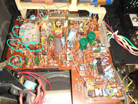
I have attached an image with the areas where changes were made.
I found the service manual, but some real pictures it will help me much.
 

Attachments

  • radio.jpg
    radio.jpg
    326.5 KB · Views: 24

mariuseek

New Member
Thank you. I already have the user manual.
I'm a beginner with the radios and some actual pictures can help me a lot to see what components have been replaced or modified.
It seems that the band is not 87.5 to 108 MHz, there are some changes and I want to restore the board close to original before start tweaking it.
 

Superduper

Moderator
Staff member
I don't understand why you think that the components have been replaced or circuitry modified. You stated that you are beginner with radios, yet you specifically identified components of interest, as if to suggest you are familiar with those components and the purposes that they serve. Honestly, nothing looks suspicious with those components to me. Your bandwidth reception issues could simply be failing components or an alignment that has drifted from factory. You can follow the instructions in the service manual to re-align the tuner, which could address the bandwidth misalignment.
 

mariuseek

New Member
I can simply see where changes were made on the board, this was not done in a professional way, that it might not be very visible in the picture. I want to adjust the tuner, that's why I want to be sure that the board to have the right parts, otherwise I might get a lot of headaches doing it.
 

JohnK11

New Member
To restore the original state of the JVC RC-727L radio board,_ obtaining pictures of the components from various angles is beneficial.This will aid in id/entifying replacements.It’ s also wise to check for tuning issues, as they may affect receptionn quality;)
 

caution

Member (SA)
You have above average talent, then. Aligning a tuner board is no small feat. I'd bet there aren't more than a couple members here that have ever done it.
 

floyd

Boomus Fidelis
I can simply see where changes were made on the board, this was not done in a professional way, that it might not be very visible in the picture. I want to adjust the tuner, that's why I want to be sure that the board to have the right parts, otherwise I might get a lot of headaches doing it.
I see what you mean . somebody really did a hack job on that tuner board.
 
  • Like
Reactions: Tinman

Tinman

Member (SA)
I only worked on getting FM on my Clairtone 7979 and it was an absolute bitch.
I was literally turning screws and bending that coil for hours a day over several days.
I kept chasing the stations up and down the tuner.
I kept another radio next to me to verify what station I was on and where I was at on the tuner.
I was so desperate when I couldn't get stereo to work I tried changing the stereo led which didn't work.
In the end I got FM/FM stereo tuned in pretty well, AM not even close and the short bands I have no idea and didn't really care because I was so happy about getting FM working.
Without the right equipment, I'd say it's damn near impossible to get all bands dialed in, kind of like solving a Rubik's cube in the dark.
 
  • Like
Reactions: floyd

floyd

Boomus Fidelis
I don't understand why you think that the components have been replaced or circuitry modified. You stated that you are beginner with radios, yet you specifically identified components of interest, as if to suggest you are familiar with those components and the purposes that they serve. Honestly, nothing looks suspicious with those components to me. Your bandwidth reception issues could simply be failing components or an alignment that has drifted from factory. You can follow the instructions in the service manual to re-align the tuner, which could address the bandwidth misalignment.
Norm if you zoom in on the pic . you can see where somebody modified some of the coils and circuit and they did a horrible job lol.
 

floyd

Boomus Fidelis
I've always wondered, do you have to download these pics to zoom in on them or is there another way?
The magnifying glass doesn't do anything when I click and open the pic.
I use my Mobile phone . when you click on the pic you can zoom in just by spreading the picture out with your fingers.
 
Last edited:

floyd

Boomus Fidelis
Norm if you zoom in on the pic . you can see where somebody modified some of the coils and circuit and they did a horrible job lol.
If you click on the picture it will then have a slideshow of better resolution pics that you should be able to zoom in on.
 

Tinman

Member (SA)
No slideshow, just the individual pic with icons of a magnifying glass, new window, full screen and download.
What I can do is magnify using windows and it enlarges the whole page.
Other than downloading it and then zooming, it's looks to be the only way.
 

floyd

Boomus Fidelis
No slideshow, just the individual pic with icons of a magnifying glass, new window, full screen and download.
What I can do is magnify using windows and it enlarges the whole page.
Other than downloading it and then zooming, it's looks to be the only way.
Yeah what sucks is you can't see enough detail in the thread pic . the higher resolution pics that you can zoom in on really explain the problem.
 
  • Like
Reactions: Tinman

Superduper

Moderator
Staff member
Norm if you zoom in on the pic . you can see where somebody modified some of the coils and circuit and they did a horrible job lol.
Floyd,

Yes, until I zoomed in, I couldn't see anything really special. Still not enough resolution for me to make out the details, but I do see one coil that looks like it's been soldered. At first glance, that doesn't look right. However, if you look at the service manual (caution supplied link to a good one) you will see that this particular coil has a center tap. I flipped the picture so that the layout corresponds to the PCB layout in the manual and compared them closely. They match up perfectly fine. These type of copper coils typically don't have center taps so a pigtail MUST be soldered somewhere in the middle to tap it. I suspect it's 100% normal. The way it's splayed out seems a bit exaggerated but tweaking and spreading the coil shape is how to fine tune those types of coils. Unfortunately, those coils are very soft and easily distorted which is why they usually are filled with foam and then wax poured over them. Anyone messing around in a tuner and handling it can very easily distort those coils inadvertently. He's asking for a photo suggesting that a photo will help him resolve his issues. Coils typically aren't marked and they all basically look the same, although I guess you can count the number of loops. Bottom line is that inductor coils are basically just a loop of wire. There is a more complex one (L5) but it's identified as 1k which is even better because it's giving a value, the others don't provide that in the parts list. Still I'd never estimate the value of an coil by looking at a photo of it. I have a whole bag full of new radio coils here, and in order for me to use any of them, I'd have to manually measure the uh value with a meter. I'm still not convinced that there's anything wrong with the actual coil components. More than likely, he has circuitry related issues, or the tuner needs an alignment badly.
 
  • Like
Reactions: floyd

mariuseek

New Member
The board was hacked, I'm 100% sure. Just because I'm a beginner doesn't mean I can't see. About the tuning, that's why I want to restore it to its original state, it will be easier if I have the components with the original values. I know it will be a challenge, but I want to do it, no matter how hard it is. At least I want to try.
From the diagram I'll try to identify the components I'm interested in on other JVC models, maybe I'll have better luck finding other picture board models.
 

Superduper

Moderator
Staff member
You are not listening. You already have the service manual, ergo, the part number for every single component you are concerned about is listed there. You can cross reference those if you think you can find some information of value. But NO IMAGE of a coil is going to give you a value. Some packaged inductor coils have listed values. But the only packaged inductor there already appears to have a 1k value provided in the service manual. The inductors that are just a slinky coil WILL NEVER HAVE a value marked on the component. The only way to provide you the value of a coil of wire is to desolder the coil from the PCB and measure it, and in doing so, will risk changing it's characteristics when it is desoldered and handled. Also that special 3-legged inductor with the center tap will surely requires on-board adjustments since that tap is not going to be precise. Tuners are not like amplifiers or other devices where the operation depends upon populating a pcb and then it works without adjustment most of the time. Tuners require adjustment and alignment after installation of the components and the tuner bandwidth does change substantially simply by tweaking the coils. Here is an image of a handful of coils from my workbench inventory. Tell me, can you ascertain the value of any of them? I'lll tell you now that you need a special version "L" which is not a local North American model, so you'll have to find someone with that boombox in the local area, probably europe I presume. Then you'll need to find someone willing to risk depopulating (desodering) those components from the pcb and measuring it's value, risking altering the tune of the radio. You'll find even far fewer people who have an LCR meter to measure the mh, and/or an oscilloscope and the match necessary to do those for you.

IMG_9765.jpg
 

mariuseek

New Member
Thanks! You gave me a lot of precious information. I found some images and see that the original inductor with the tap has 3 windings and not 4 and that 1k inductor should be one piece like a fat ceramic capacitor. The coil on that plastic tube is missing the ferite core. It looks like they tried to modify and tuning my board to cover the 65.8-74 mhz band. I wanted back to 87.7-108 mhz.