JVC M90 deck problem

Tinman

Member (SA)
Like I said above, I also thought those resistors stood off the board and used socks but obviously they didn't.
Maybe it's an older M90 before they started that practice, who knows.
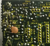
That said, even though 703 and 704 are mounted normally, there is no discoloration to the board and the yellow print is in excellent shape.
The Rubycon cap next to 703 has a little darkness on it which could be from heat but it's hard to tell.
 

Superduper

Moderator
Staff member
These boomboxes are all 45-50 years old now, and those fusible resistors have proven to be high maintenance items. With regards to FR704 in fact there is a good chance that it blows whenever the main drive belt fails, so there's a good chance that your resistor(s) aren't even original. It's good that your PCBs have no discoloration, but if those resistors go, there could be significant discoloration, scorching, and sometimes, can even result in a hole on the PCB damaging it beyond repair. Whether front or rear mounted, I've always only ever seen those fiberglass flameproof sleeves on the leads, and the resistor mounted stand-off style. Since most parts are no longer available, it's my suggestion that all such resistors should be reaffixed by standing them off from the PCB as there's no sense to risk damage to parts that are no longer available on a boombox model that is quite valuable.
 
  • Like
Reactions: BoomboxLover48

BoomboxLover48

Boomus Fidelis
Here is the picture of a completely scorched original FR704 in the M90. I opened this unit for the first time and was in like new condition with not even a hairline scratch on it. It only had a small dent on the Al trim above the tuning dial.

This is my second time replacing the FR704 on the same.

FR901 on the power supply board also I mounted an inch away from the PCB.
1738387635570.png

1738385396704.jpeg
 

Attachments

  • 1738384852106.png
    1738384852106.png
    1 MB · Views: 4
Last edited:

Superduper

Moderator
Staff member
I wonder if the picture Royce is showing is for a non-JW model, because that resistor isn’t even represented in that pcb diagram. Based on its location, I wonder if it isn’t some kind of bleed off safety resistor or other type of component originally?
 

BoomboxLover48

Boomus Fidelis
Good catch!
I made a terrible mistake here! :sadno: :-/

I went back and checked it. I saved that resistor.
I accidentally replaced a 2.2 mega ohm (reading 2.42 Mega ohm) resistor by mistake for FR901.

I don't see that resistor in the diagram I have.
 
Last edited:

Superduper

Moderator
Staff member
Good catch!
I made a terrible mistake here! :sadno: :-/

I went back and checked it. I saved that resistor.
I accidentally replaced a 2.2 mega ohm (reading 2.42 Mega ohm) resistor by mistake for FR901.

I don't see that resistor in the diagram I have.
Based on the location, and the resistance, that seems like it’s almost surely a safety resistor. On many stereos, a 2.2 meg resistor is often used to connect one leg of the input line to chassis ground to bleed any static accumulation off of the set while not providing enough current to be harmful or even noticeable by the user. The 2.2m value resistor reading 2.42 is probably insignificant, especially in that application and maybe not unusual as old carbon type resistors aren’t the most precise to begin with.
 
  • Like
Reactions: BoomboxLover48

Tinman

Member (SA)
I relocated all of my 704s to the back side and stood them off the boards for easy replacement if need be so no worries there.

Good catch caution.