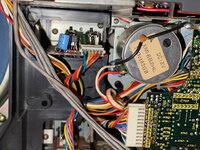
JVC M90 deck problem

BoomboxLover48

Boomus Fidelis
My JVC M90 was all working fine after replacing one fusible resistor.
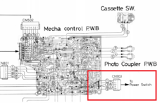
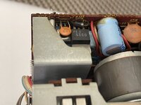
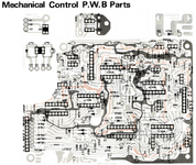
That fusible resistor can be seen at the top edge of the mechanical control board PCB.

A few days ago, I just brought out and when powered on it was not resetting with the clicking sound. I knew there is some problem with it.
It was not playing cassette, and the deck seemed nonfunctional.

Radio works well with no problem. So, I wanted to check if that fusible resistor again went bad and found that it was all fine.
Later, caution advised me to check all the other fusible resistors on the Mechanical Control Board and they all looked good.

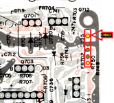
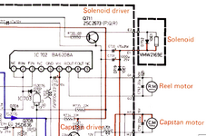
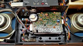
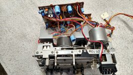
The connector CN 903 pins on the mechanical control board were checked for DC voltage

See the third diagram where CN 903 pins are marked with yellow dots, green dots ending with yellow dot.

Let us mark it 1 to 5 from top yellow to bottom yellow.

Pin#3 -17.31V, pin# 4-16.58V and pin #5 -0.00V. There is no voltage on the #5 pin.

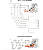
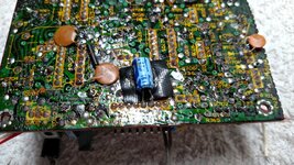
Eric wanted me to check the power supply and found another fusible resistor FR 901 (2.2 ohms) with no continuity.
Diode 905 was all fine along with all other diodes on the power supply.

Today, I replaced FR 901 (2.2 ohms) and when powered on, the deck was not cycling and resetting.

Deck has all new belts.

I was wondering why the deck is not resetting and functioning like it should!

Any help to solve this deck problem is greatly appreciated.
1738035315342.png


1738023878268.png


1738023916300.png
1738024904225.png
 
Last edited:

Superduper

Moderator
Staff member
When you say you checked all of the fusible resistors, did you just do a visible examination, or did you check for voltage at both sides of the resistors? Don't just check for resistance, because they might not show a fault unless they are passing current. Also, you may want to verify the belts are in proper order. I know you said the belts are new, but check them anyways. Also if motor is blown, it obviously can not do any resetting. Just apply power through a 9V battery to the proper terminals and verify that it actually spins up; doesn't take long to do this check and allows you to check this off on list of possible failure points. See if you can induce play by bringing pin 14 of IC701 HIGH, you can do this by injecting 5V through a resistor, try ~1k or thereabouts.

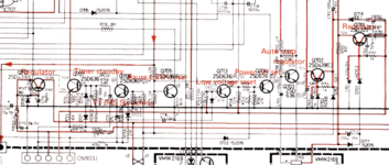
The only thing further I can suggest beyond that is to check to make sure all of the voltages spec correctly (especially at the transistors leads in the attached screenshot). This to ensure that your regulators are working properly. The fusible resistors should've prevented damage to the regulators but sometimes, especially if they weren't the correct resistors, might trip too late to prevent damage.

Pin 5 appears to be related to muting circuit that mutes the amplifier when the main power button is switched off.

Screenshot 2025-01-27 at 11.51.15 PM.png
 
  • Like
Reactions: BoomboxLover48

BoomboxLover48

Boomus Fidelis
Thanks so much Norm!
I was only checking the continuity of those fusible resistors. I will go ahead and check voltages on them soon.

Belts are in proper order. It was all working fine after I replaced it.

Can I try powering the motor in parallel with the + to the red wire and - to white solder joints?

1738086699287.jpeg


~Royce
 
Last edited:

BoomboxLover48

Boomus Fidelis
Motor is working when 9.0V was applied.

I made an interesting observation.
When I press the power button, I hear a faint click but not loud like the noticeable 'clunk" sound it makes when it normally cycles and starts.
Is the relay stuck for some reason? Seems like it is trying to do something and not fully making it happen.

Even though I worked on M90 several times, I forgot where the mechanical part of it is and how it operates when you power it.
 
Last edited:

caution

Member (SA)
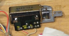
It's not a relay, but a solenoid. I can't remember where it is on the deck but it looks like this:

solenoid.jpg

The thing sticking out on the right with the little pin in it is the shaft that moves when the coil surrounding it energizes. See if you can move it manually. It may be fine, but the part it connects to is binding.
 
  • Like
Reactions: BoomboxLover48

Superduper

Moderator
Staff member
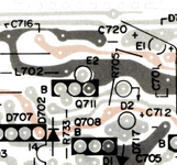
The solenoid is what clicks, PN#65 on the exploded view diagram. If the noise is fainter than normal, I would definitely look into that and see if it's free and not bound up in some way. Also you may want to verify FR704 and transistor Q711. FR704 is where the solenoid sources it's current and Q711 is where it sources the solenoid ground. Can the resistor or that transistor supply the current it needs? Again, sometimes, resistor faults don't show up until current is flowing.
 
  • Like
Reactions: BoomboxLover48

BoomboxLover48

Boomus Fidelis
I left the power switch on and pugged it in and out to hear the faint sound of something activating with a weak humming sound. Volume was set at minimum.

I will see if the motor is also turning when this happens.

After that I will remove the deck and check if the solenoid plunger is stuck or not.
 
Last edited:

BoomboxLover48

Boomus Fidelis
The solenoid is what clicks, PN#65 on the exploded view diagram. If the noise is fainter than normal, I would definitely look into that and see if it's free and not bound up in some way. Also you may want to verify FR704 and transistor Q711. FR704 is where the solenoid sources it's current and Q711 is where it sources the solenoid ground. Can the resistor or that transistor supply the current it needs? Again, sometimes, resistor faults don't show up until current is flowing.
FR 704 is new; I will check Q 711 soon.
What voltage I should read for the 1738127183327.png
it's not showing anything on the diagram.

1738125285841.png
1738125683686.png
 
Last edited:

Superduper

Moderator
Staff member
FR 704 is new; I will check Q 711 soon.
What voltage I should read for the View attachment 60068
it's not showing anything on the diagram.

The transistor base is already marked for you on the board.
The transistor emitter should be tethered to ground so it should read 0 volts or should test continuity when tested from E to ground (system off please to protect your meter).
The transistor collector should read somewhere approximating system voltage (minus the voltage drop across a diode and the solenoid coil, maybe 1-2V less than system voltage).

When powered on, the transistor base should receive a temporary H pulse of somewhere between 3 to 5 volts. You may need a fast digital meter or an analog meter to see it. If digital meter, it should be set to a manual scale rather than autoscale if available. Or an oscilloscope.

Due to the dynamic nature of the readings, it's why no specs are published. But that is the approximate voltage behavior to be expected if with everything normal. However, those readings won't verify transistor functionality, since all of those readings might be correct and still not work properly. However unusual readings might indicate other circuitry issues or clues. But going back to that transistor, for that reason, the transistor can be tested with a multimeter using the diode settings on your meter. Google youtube to see how to do that. If you have a cheap component tester, you can test them either in or out of circuit (with wire leads) and they are pretty accurate in identifying the component and it's values. Search on eBay "component tester" and they are all over there around $15 shipped. Almost all are based on the Atmel Mega328p arduino type microcontroller. I doubt you can build your own for the price you can buy and certainly not worth the trouble to make one yourself.

Although you installed a new FR704, it does not necessarily mean you should overlook or presume that it hasn't developed an issue again. The solenoid is a high draw component and if it is humming, then it may be binding and drawing too much current. If the resistor resistance has changed, especially higher value, then it could result in passing insufficient current to the solenoid. It should still be verified, never presume. Honestly, all this happens in a mere instant. The solenoid output pulse from the IC701 duration appears to only be 3/4 to 1 revolution of the capstan, if I recall correctly, so not long. Obviously, the capstan needs to spool up during this time.

If everything looks correct, that the solenoid is triggering momentarily but you never see the capstan motor spool up, then you need to consider whether the capstan drive circuit is working properly. This involves regulator Q712, fusible resistor FR703 and driver transistors Q709/Q710. Taking the base of Q709 high (inject 3 to 5 volts) should cause the capstan motor to spin up.

That you can hear a slight click (like the solenoid momentarily engaging) is a promising sign because it suggests that IC701 is sending a trigger pulse to the solenoid. IC701 is unobtanium so that is the one chip that could brick your deck if dead, although I suspect that some arduino programmer should be able to rig up a new micro-controller replacement without too much difficulty to substitute that chip, maybe someday if the demand is high enough. Your issue could simply be unrelated to the solenoid and due to the capstan not spooling up. The click that one normally hears is the deck resetting at the end of a completed reset cycle. Everyone that has had a deck with broken belt and not reset knows that familiar clack when reset is complete after manually rotating the flywheel. So the whole process.... click of solenoid --> clack of the mechanism reset all happens in 1 revolution of the capstan. You might be only hearing the initial click and missing the louder clack.
 
  • Like
Reactions: BoomboxLover48

BoomboxLover48

Boomus Fidelis
I will replace the FR704 (4.7 ohms/0.25W), will check the R733 resistor soon and see if the value has changed.
It is 100 Ωs right?
 
Last edited:

BoomboxLover48

Boomus Fidelis
SUCCESS!:rock:

Thank you, Norm and Eric!:bow:

It was all a bad FR 704 again! Bad solder also!
I lubed the solenoid end slight metal friction areas with light Lithium grease also.
 
Last edited:
  • Like
Reactions: Superduper

Tinman

Member (SA)
I blew a few 704 resistors while I was testing my M90.
I was leaving the power button depressed and unplugging then plugging the power cord in.
It was a few years back and I could be wrong but I think that's what was popping the resistor on me.
I ended up soldering it on the back side of the board so I could replace it easier.
 

BoomboxLover48

Boomus Fidelis
I blew a few 704 resistors while I was testing my M90.
I was leaving the power button depressed and unplugging then plugging the power cord in.
It was a few years back and I could be wrong but I think that's what was popping the resistor on me.
I ended up soldering it on the back side of the board so I could replace it easier.
I am not sure if plugging and unplugging with power button on would blow the FR704. Technically it shouldn't, right?

FR704 was always on the back side of the board. I have another M90 and that also has it on the backside. Luckily the original FR704 is still intact on it with no issues. All I did was belt replacement on that.
 

caution

Member (SA)
FR704 always gets warm under normal operation when current flows through it, but the key is, it shouldn't draw current for more than about one second - enough time to advance the drive gear to reset the deck (and shut off the solenoid), but also not enough time to let it get too hot. If you pointed a thermal camera at it on a working M90 you'd definitely see it get warm for a moment. But without a belt it's not going to turn the gear, it's going to easily fry. I remember when I worked on mine I held my finger on it when I turned it on without a belt to see how long it took to get hot and had to let go after a couple of seconds.
 
  • Like
Reactions: BoomboxLover48

BoomboxLover48

Boomus Fidelis
The front side where normally FR704 was to be placed is a bit crowded. May be that is the reason it was put on the rear side of the mechanical control board.
1738250852780.jpeg
 
Last edited:

Superduper

Moderator
Staff member
The rear side where normally FR704 was supposed to be is a bit crowded. May be that is the reason it was put on the rear side of the mechanical control board. There is some room but not much.

I suspect the reason for locating on the backside is to keep the heat away from the other components. As eric said, the resistor generates a lot of heat, and it is only designed for momentary current flow. If something is amiss and the solenoid fails to release timely, that resistor is designed to burn up. That's why it has fiberglass flameproof insulation, and is stood off away from the PCB to prevent scorching the pcb, which seems to happen a lot regardless. For this reason, it is reasonable to suggest to recheck the belt to make sure that it is not loose or possibly slipping a bit which could cause delayed solenoid release. I know you said it was new, but hey, you also said you just replaced the resistor too right? Incidentally, the resistor is undersized on purpose. If you put in a large 2w resistor, it probably would never blow, but then the regulators or the solenoid, or something else will likely blow. During use, if the resistor got hot because the solenoid didn't release fast enough, the heat will cause the resistor to begin breaking down and this usually causes the resistance to begin creeping higher.
 
  • Like
Reactions: BoomboxLover48

BoomboxLover48

Boomus Fidelis
Very good information!

I was also wondering why this happened!
I was playing this M90 after a year or so and was busy with my Panasonic RX7000s and RX7200.
I will check my other M90 and see if that is playing cassette or not.

I will check my files and see what size belts I used.
I used 9.3" medium flat belt

From what I remember it was not slipping at all.
I even pulled it to see if it is not too tight or loose and made sure it is good.
 
Last edited:

Tinman

Member (SA)
I am not sure if plugging and unplugging with power button on would blow the FR704. Technically it shouldn't, right?

FR704 was always on the back side of the board. I have another M90 and that also has it on the backside. Luckily the original FR704 is still intact on it with no issues. All I did was belt replacement on that.
Not on mine.
I have four M90s and I don't remember any being mounted on the back side.
I haven't had one apart in at least a few years but found old pre disassembly pics of one of them and it clearly shows that it's mounted on the front side.
Possibly some were and some weren't, I don't know.
I did think that they were all mounted off the board with the insulated socks but this one isn't even mounted that way.
I thought I was being smart and innovative mounting them on the back.

As far as the resistor blowing, it's possible I had the belt off while troubleshooting and that was the reason it kept blowing but again, it was a while ago so it's hard to remember.
If you wanted to try depressing the power button and unplugging it then plugging it back in, that would tell for sure :)

IMG_20200520_183015097.jpg
IMG_20200531_121048778_HDR.jpg
IMG_20200606_143740406.jpg
 
  • Like
Reactions: BoomboxLover48