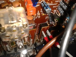
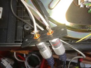
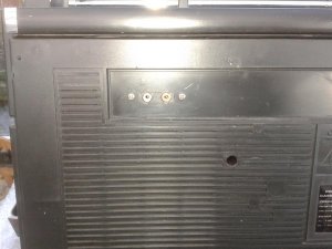
I'm going to just flat out say it.... there is NO WAY that anybody, anywhere, anyplace, can look a a photo of a boombox circuit board, and tell you which pad to connect to, which wire to cut/splice, which trace to cut. It would be hard enough to look at a blowup of a schematic diagram, but just looking at a photo, it would be impossible. The exception is that IF someone were to have that exact same boombox in front of them, figure it out, and then post a closeup to you of how it's done. Other than that, YOU would have to have enough technical expertise and skills to be able to figure out where to tie in. That's because EVERY SINGLE MODEL or variant of that model is going to be different. There is no modular system or interface like you would expect when assembling a modern computer. And although one can sometimes "presume" that red=pos and black=neg/ground, it is by no way guaranteed, and beyond +/-, there simply is no standard wiring convention to go by for any other wire connection. Also black neg is different than black ground. Giiven this, the only way to do a mod like this is to test and trace to find the audio signals. That is a hands on process and not a look at a photo of one side of a board and tell you what to do type of thing.
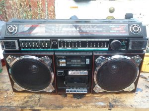
On my Wards retrofit, that refit, if done exactly like that, would only work for that particular model. While it could technically work on virtually any model, the exact method of where to splice into the radio signals varies depending upon the model. I showed it not to suggest that you do it exactly like that on any other boombox, rather it was to demonstrate the overall process you would employ and while a similar mod could be employed on say, a sanyo boombox, you would still need to customize the install and retrofit, and this means first finding out the exact audio signal path.
On your particular boombox, here are 2 possible methods I would approach it:
1. First, find the MPX decoder chip. It would usually be one of the IC's on the tuner board. Look up the datasheet and find the audio L/R output signals pins. Follow those traces (through caps and resistors if necessary) until it terminates at the function selectors. That would usually be where it would be tapped. However, it MUST be confirmed by way of an audio signal tracer. Cut these traces and they would be where you would splce into. On some models with a separate tuner board, this is much easier since the audio signal lines would be tethered by wires and they are easier to find.
2. I found a larger image online where I could see the buttons. You have No AUX, No Phono. Howver, you DO have a power button. That is good because on many boomboxes, the function selector on tape setting shuts the boombox down. It looks like it is possible to power on the boombox on the tape setting using only the power switch. If that is the case, then you just need to find the audio signal pins of that tape switch. The simplest way is to use an audio signal generator, and probe the pins from behind the switch. I'm not going to go into a whole classroom lecture on how to do that. But that is how I would approach it. This is the simpler of the two methods since it requires no switching jack, just a standard stereo 1/8" jack (or even RCA's) and tap into the correct side of the tape switch. Obviously, you should not have anything connected to the new aux connections when a tape is playing and make sure to use shielded cables.


 Much respect to :superduper: ,you, and your Dad for pulling together to make it work. Great job guys. Thats what Boomboxery is all about.