In an effort to prepare for the International Boombox Meet in Las Vegas, I have made a list of radio's I will be taking and work that needs to be done to take them.
I'm sure you remember this build "Helix HX-4700 Custom".
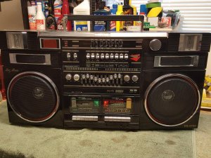
In the time that has past since I built this radio, it has hit the streets a few times. One of them being at the Relay For Life event last summer and another time at the beach.
Most of it's time is spent plugged into the wall.
But what I noticed is, the LED system I built was pulling to much off the power supply. Over a short period of time, the radio would start cutting in power and the lighting would dim out.
So, I have been formulating a plan to resolve this issue.
What I came up with is the simplest way to go and that is to set the LED system up on it's own battery supply and let the stereo run on it's 10 D cells.
The issue I faced is that I set up the LED's to run off of 15V (10x 1.5v D cells).
In order to get 15v worth of power, the plan was to use two 9v batteries (18v) and cut the power down to 15v for the LED's. LED's are very power specific. Resistors are used to get the right power and I set all of them up to run on 15v. So without taking it all out and changing the resistor values on all the LED's, this is a cheap way of doing this.
To begin with, I bought a few items to do this job...
Two 9v batteries (these are cheapies for testing, I will be running Duracell's in the finished product)
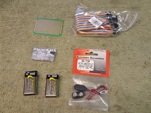
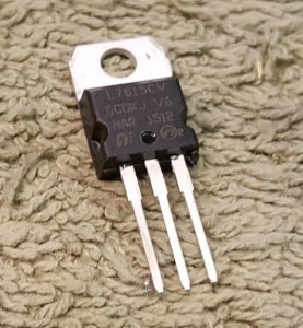
One voltage regulator IC chip
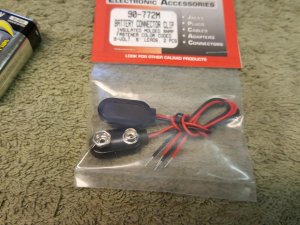
Two 9v battery connectors
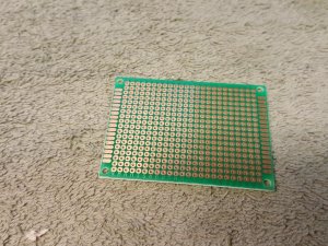
One prototyping breadboard for testing
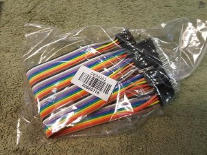
A bundle of test leads
The voltage regulator IC cuts the input voltage, in this case, 18 volts, down to a pre-set voltage of 15v. You can buy them in almost any voltage setting you need. I watched a youtube video on how this works here
The nice part about this set up is, if the two 9 volt batteries don't last very long, I can simply add a third 9v, upping the input to 27 volts and still get 15 volts out. Hopefully the two 9 volt's will last a long time, but only testing will let me know.
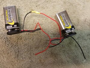
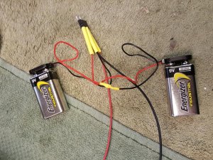
To start with, I wired up the batteries to double the voltage to 18v
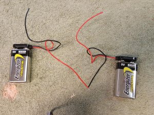
Tested the battery voltage...
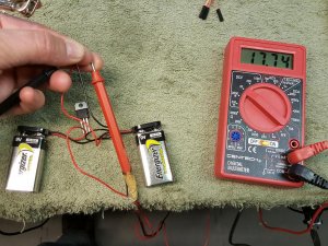
Next I set up the breadboard with my components to test the setup before soldering it all together
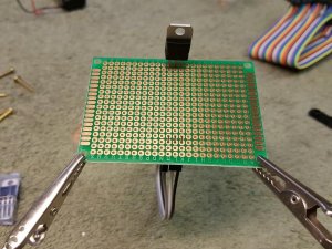
I connected the batteries to the voltage regulator
Left pin Power IN, Center pin GROUND, Right pin Power OUT
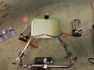
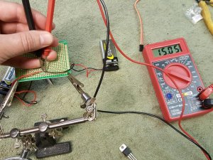
And test...
Next was to solder the battery connectors together and add shrink tubing.
I then had to locate the power and ground wire for all the LED lighting from the on/off switch. I added connectors to them so when I remove the back of the radio I can unplug them since the two 9v batteries will be going in the spare tape compartment on the rear case.
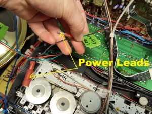
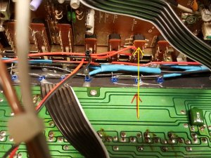
These wires come from the re-purposed "Beat Cancel" switch on the front of the radio.
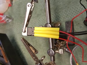
Now to solder the 9v battery wires to the voltage regulator IC (Left In, Center Ground, Right Out)
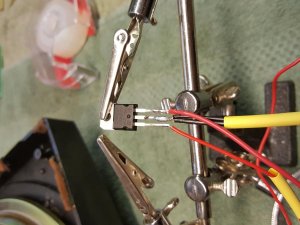
Add some shrink tubing to prevent shorting...
Wired with the 9 volts...
Now, I simply plug into the LED power leads on the radio...
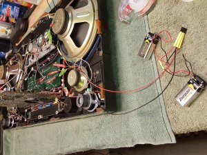
Press the button AND presto...LIGHTS!
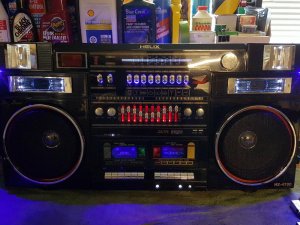
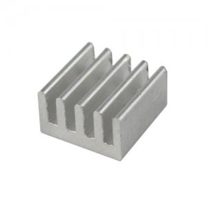
As expected, the IC chip run's hot. So I have ordered a tiny heatsink (3/4" x 3/4") to attach the IC to. Then I will mount it in the box and test it to see how long it takes to eat two 9 volt batteries.
I'm not really worried if it only lasts a few hours. This radio is more of a novelty and less of my "Go To" box. I have plenty of radio's for that. But I think this radio needs to ROCK Las Vegas under the neon lights!
I'm sure you remember this build "Helix HX-4700 Custom".

In the time that has past since I built this radio, it has hit the streets a few times. One of them being at the Relay For Life event last summer and another time at the beach.
Most of it's time is spent plugged into the wall.
But what I noticed is, the LED system I built was pulling to much off the power supply. Over a short period of time, the radio would start cutting in power and the lighting would dim out.
So, I have been formulating a plan to resolve this issue.
What I came up with is the simplest way to go and that is to set the LED system up on it's own battery supply and let the stereo run on it's 10 D cells.
The issue I faced is that I set up the LED's to run off of 15V (10x 1.5v D cells).
In order to get 15v worth of power, the plan was to use two 9v batteries (18v) and cut the power down to 15v for the LED's. LED's are very power specific. Resistors are used to get the right power and I set all of them up to run on 15v. So without taking it all out and changing the resistor values on all the LED's, this is a cheap way of doing this.
To begin with, I bought a few items to do this job...
Two 9v batteries (these are cheapies for testing, I will be running Duracell's in the finished product)

One voltage regulator IC chip

Two 9v battery connectors

One prototyping breadboard for testing

A bundle of test leads

The voltage regulator IC cuts the input voltage, in this case, 18 volts, down to a pre-set voltage of 15v. You can buy them in almost any voltage setting you need. I watched a youtube video on how this works here
The nice part about this set up is, if the two 9 volt batteries don't last very long, I can simply add a third 9v, upping the input to 27 volts and still get 15 volts out. Hopefully the two 9 volt's will last a long time, but only testing will let me know.
To start with, I wired up the batteries to double the voltage to 18v

Tested the battery voltage...

Next I set up the breadboard with my components to test the setup before soldering it all together

I connected the batteries to the voltage regulator
Left pin Power IN, Center pin GROUND, Right pin Power OUT

And test...

Next was to solder the battery connectors together and add shrink tubing.

I then had to locate the power and ground wire for all the LED lighting from the on/off switch. I added connectors to them so when I remove the back of the radio I can unplug them since the two 9v batteries will be going in the spare tape compartment on the rear case.

These wires come from the re-purposed "Beat Cancel" switch on the front of the radio.

Now to solder the 9v battery wires to the voltage regulator IC (Left In, Center Ground, Right Out)

Add some shrink tubing to prevent shorting...

Wired with the 9 volts...

Now, I simply plug into the LED power leads on the radio...

Press the button AND presto...LIGHTS!

As expected, the IC chip run's hot. So I have ordered a tiny heatsink (3/4" x 3/4") to attach the IC to. Then I will mount it in the box and test it to see how long it takes to eat two 9 volt batteries.

I'm not really worried if it only lasts a few hours. This radio is more of a novelty and less of my "Go To" box. I have plenty of radio's for that. But I think this radio needs to ROCK Las Vegas under the neon lights!


 misread the bloody title! Oh well, some pics of your workshop will have to suffice!


 )
)