Custom light for deck door + tutorial + WARNING
- Thread starter LJV
- Start date
You are using an out of date browser. It may not display this or other websites correctly.
You should upgrade or use an alternative browser.
You should upgrade or use an alternative browser.
- Status
- Not open for further replies.
Northerner
Boomus Fidelis
jimmyjimmy19702010
Member (SA)
AE_Stereo
Member (SA)
blu_fuz said:All boomers should have a lit tape deck
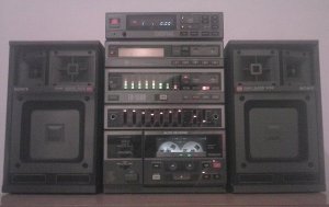
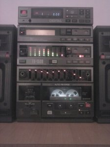
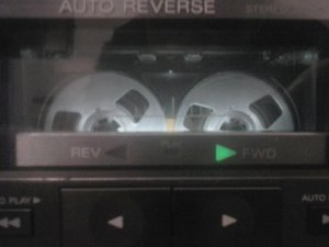
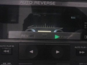
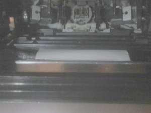
 . The Cassette is the centerpoint of a boombox. So the cassette must be given the attention it deserves - no better way than to illuminate the tape window.
I made it for my RX-7000. It makes you more happy!
You can also try to reduce the LED light output by adding more resistance in series.
I masked one out of 3 LEDs with a black tape to reduce light!
kraftmatic
Member (SA)
Very nice! I have an FH-15 that I'm about to begin restoring, maybe I'll try a similar set up. Do you have any photos of the LED installation?
devol-toni
Member (SA)
-GZ- said:I like it. Would look cool with a dim red too to match the LEDs.
That is why I've returnet to plain white, that makes any tape visible in its original color.
I have another much more complicated but alot cooler idea which I won't try - to put 3 color leds - white, green and red, and to connect them in that wat thay if deck is on idle the light is white, if it is playing, the light is green, if recording red. That would be supercool, but would require too much work.
This subtle diffuse and dimed light is more than enough.
bklyn sound
Requiem Æternam
-GZ-
Member (SA)
I hear ya. Nice work man. Great looking unit tooLJV said:I've tried days ago both orange to match leads, or green to match play led, and it works, but looks obviously pimped.
That is why I've returnet to plain white, that makes any tape visible in its original color.
I have another much more complicated but alot cooler idea which I won't try - to put 3 color leds - white, green and red, and to connect them in that wat thay if deck is on idle the light is white, if it is playing, the light is green, if recording red. That would be supercool, but would require too much work.
This subtle diffuse and dimed light is more than enough.
kraftmatic
Member (SA)
Yes please! I would very much appreciate a tutorial for the deck. Thank you!LJV said:Just seen that I've lost reply to two forum memmbers who were inquiring for details. Damn imageshack. Sorry.
However, I'm about to add lit up tape counter too, so I will make a small tutorial with much more photos for both deck door and counter.
I need a bit time, since I'll try different config to make this light source somehow firmly attached but detachable. I'm trying to construct a diy shell for it. If you're in the process of restoration of your FH, just get it in shape. This light add-on requires nothing but removal of casing cover.kraftmatic said:Yes please! I would very much appreciate a tutorial for the deck. Thank you!
BTW, I've tried to light up counter, but it wasn't satisfactory at all, so I gave up. No matter where the light source is placed, it either lights up only fore-coming row of dials (which is unwanted), or it is too dark, or with so much back light that you can't see the numbers.
kraftmatic
Member (SA)
Okay, thanks for the advice. I'm waiting for the new speaker surrounds to arrive before I start on the restoration.LJV said:If you're in the process of restoration of your FH, just get it in shape. This light add-on requires nothing but removal of casing cover.
OK, here is the tutorial.
I've gone trough a lot of work, even tried another position of LED light, which had benefits when it matters fixing, but the light couldn't span nicely, so I've ditched it.
As you've seen in initial posts in this topic, I've glued self adhesive led strip at the internal cover of control panel pcb at deck door. It worked fine, but those self adhesive ones are too narrow, and adding filter is problematic.
In version shown in this tutorial, I've picked same position for LED lighting, but instead I've used one on PCB, with span of diodes that matches position of reel axles, and mounted it on custom made holder.
LED module as it looked like when I bought it.
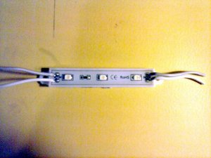
First thing I've done was to remove LED pcb from thick white module, because it is useless and only creates problems. After that, I've removed pieces of wires on both sides, because they are at 90 degrees, and too thick, without sufficient elasticity. Make sure to mark + and -, because they are hardly visible.
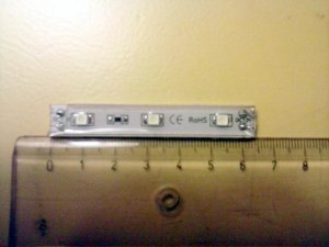
Next step was to remove silicone cover on top and around the soldering points (on the left side). Quite easy, but caution is necessary. Than I've removed original wires, and soldered a piece of shielded audio cable instead. It is elastic and durable, ideal for power supply of LED.
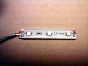
Note: When you finish soldering, apply a layer of hot glue over contacts and wires (not thicker than pcb and silicone protection) in order to prevent snapping of wires over time and possible short-circuit. You can do the same on the other side of the pcb with contacts meant for extension, after you've cut them all the way down. Whole assembly can be taken out periodically and checked for damage, in less than a minute.
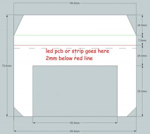
Holder is deliberately made of soft 0.3mm plastic, since there is a tight space between deck door frame and the control panel attached on them. This space enables to guide in something thin, and to have constant pressure, which disables motion and holds thin piece of plastic, similar to how slots on mainbroads hold the cards.
I've used plastic from this sort of filers, flexible but not paper thin. Just right.

The drawing shows dimensions of holder. After you cut it out, draw the blade of cutter slightly over green and red line. Just slightly. Intention is to enable plastic to bent easily on those spots, without breaking. I’ve used 0.3mm thick plastic from some paper filer. Do not go over 0.4, because it will give you trouble.
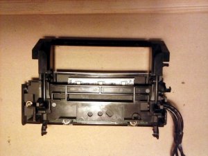
Approximate position of LED pcb relative to deck door frame, and the back cover of the control panel.
The photos show how to fold and form the shape of holder, and which part to cut out, as well as where and how LED pcb is glued. When the glue has firmed, guide the cable beneath the spring in door frame on the lest side, just on top of where the rest of the cables go.
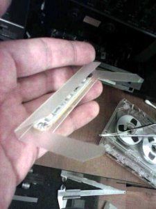
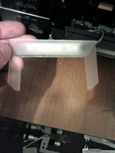
Than take holder and carefully slide it in space between door frame and control panel cover, until it reaches bottom. The top of it should be some 2mm below the bottom of aperture of door window.
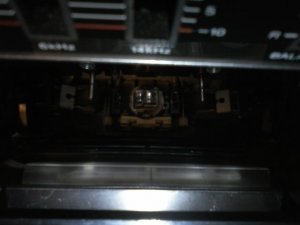
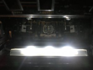
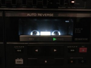
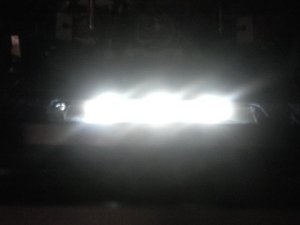
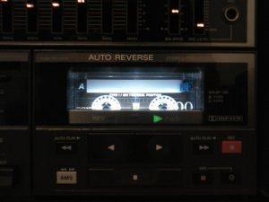
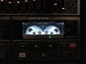
Default light. Looks too bright on photo since it's been taken in the dark, but with dimmed or normal light in the room, it has it's charms, since it reminds on old neon lit shop windows, and you can really, see trough tape if it is transparent. Playing with filters is a matter of personal liking and inspiration.
After you’ve done this, there will still be a bit of space to slide in thin color filter on both sides of the holder.
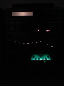
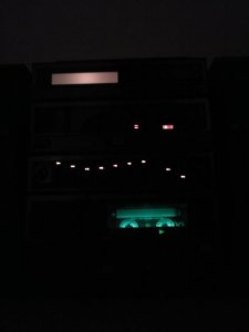
I had no orange plastic foil for filter, so I've put yellow and red, to create orange, but it turned out too thick and too dimmed.
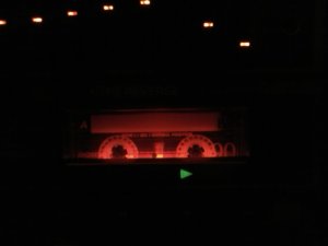
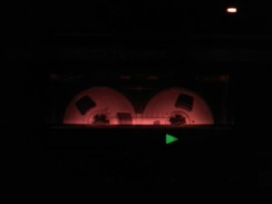
As you can see on pics, I’ve tried both green and orange filters, as default colors on FH.
If you are lucky, perhaps you’ll find colored piece of plastic for holder, that will need no additional filter.
I haven’t made pics of where to solder other end of the cable, since it is more than obvious that best place to do it is where the cable powering capstan motor 12V is soldered. Red is + white is -. Make sure not to make a mistake, because LEDs are not bulbs, and polarity is important.
Anyway, it took me a lot of time on experimenting, but basically, it takes couple of hours to finish it all, and wiring is extremely simple.
Most important of all, you don't need to take apart door, not even to remove the decorative window. All that is required is to remove the deck cover in order to solder the other end of the cable. Everything else is intended to be assembled outside and than just placed in, without any screws, glues, hot glue etc.
Make sure to keep unit both unplugged and turned off while wiring.
If there is anything important I forgot to mention, please feel free to ask.
Enjoy, and share your pics!
*I've been editing, added few important things, so make sure to re-read before you're up to it.*
I've gone trough a lot of work, even tried another position of LED light, which had benefits when it matters fixing, but the light couldn't span nicely, so I've ditched it.
As you've seen in initial posts in this topic, I've glued self adhesive led strip at the internal cover of control panel pcb at deck door. It worked fine, but those self adhesive ones are too narrow, and adding filter is problematic.
In version shown in this tutorial, I've picked same position for LED lighting, but instead I've used one on PCB, with span of diodes that matches position of reel axles, and mounted it on custom made holder.
LED module as it looked like when I bought it.

First thing I've done was to remove LED pcb from thick white module, because it is useless and only creates problems. After that, I've removed pieces of wires on both sides, because they are at 90 degrees, and too thick, without sufficient elasticity. Make sure to mark + and -, because they are hardly visible.

Next step was to remove silicone cover on top and around the soldering points (on the left side). Quite easy, but caution is necessary. Than I've removed original wires, and soldered a piece of shielded audio cable instead. It is elastic and durable, ideal for power supply of LED.

Note: When you finish soldering, apply a layer of hot glue over contacts and wires (not thicker than pcb and silicone protection) in order to prevent snapping of wires over time and possible short-circuit. You can do the same on the other side of the pcb with contacts meant for extension, after you've cut them all the way down. Whole assembly can be taken out periodically and checked for damage, in less than a minute.
Holder is deliberately made of soft 0.3mm plastic, since there is a tight space between deck door frame and the control panel attached on them. This space enables to guide in something thin, and to have constant pressure, which disables motion and holds thin piece of plastic, similar to how slots on mainbroads hold the cards.
I've used plastic from this sort of filers, flexible but not paper thin. Just right.

The drawing shows dimensions of holder. After you cut it out, draw the blade of cutter slightly over green and red line. Just slightly. Intention is to enable plastic to bent easily on those spots, without breaking. I’ve used 0.3mm thick plastic from some paper filer. Do not go over 0.4, because it will give you trouble.

Approximate position of LED pcb relative to deck door frame, and the back cover of the control panel.

The photos show how to fold and form the shape of holder, and which part to cut out, as well as where and how LED pcb is glued. When the glue has firmed, guide the cable beneath the spring in door frame on the lest side, just on top of where the rest of the cables go.


Than take holder and carefully slide it in space between door frame and control panel cover, until it reaches bottom. The top of it should be some 2mm below the bottom of aperture of door window.


Default light. Looks too bright on photo since it's been taken in the dark, but with dimmed or normal light in the room, it has it's charms, since it reminds on old neon lit shop windows, and you can really, see trough tape if it is transparent. Playing with filters is a matter of personal liking and inspiration.


After you’ve done this, there will still be a bit of space to slide in thin color filter on both sides of the holder.


I had no orange plastic foil for filter, so I've put yellow and red, to create orange, but it turned out too thick and too dimmed.


As you can see on pics, I’ve tried both green and orange filters, as default colors on FH.
If you are lucky, perhaps you’ll find colored piece of plastic for holder, that will need no additional filter.
I haven’t made pics of where to solder other end of the cable, since it is more than obvious that best place to do it is where the cable powering capstan motor 12V is soldered. Red is + white is -. Make sure not to make a mistake, because LEDs are not bulbs, and polarity is important.
Anyway, it took me a lot of time on experimenting, but basically, it takes couple of hours to finish it all, and wiring is extremely simple.
Most important of all, you don't need to take apart door, not even to remove the decorative window. All that is required is to remove the deck cover in order to solder the other end of the cable. Everything else is intended to be assembled outside and than just placed in, without any screws, glues, hot glue etc.
Make sure to keep unit both unplugged and turned off while wiring.
If there is anything important I forgot to mention, please feel free to ask.
Enjoy, and share your pics!
*I've been editing, added few important things, so make sure to re-read before you're up to it.*
- Status
- Not open for further replies.


