Big Ben deck playback too fast
- Thread starter docs
- Start date
You are using an out of date browser. It may not display this or other websites correctly.
You should upgrade or use an alternative browser.
You should upgrade or use an alternative browser.
- Status
- Not open for further replies.
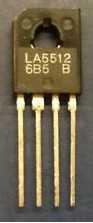
This would be the image if the pin out was the other way around.

However, I am still using the correct lead on the motor as the -pitch because I can see on the pcb that it is connected to the -pitch of the motor pin.
View attachment 33080
However, I am still using the correct lead on the motor as the -pitch because I can see on the pcb that it is connected to the -pitch of the motor pin.
View attachment 33080
Attachments
Dave,
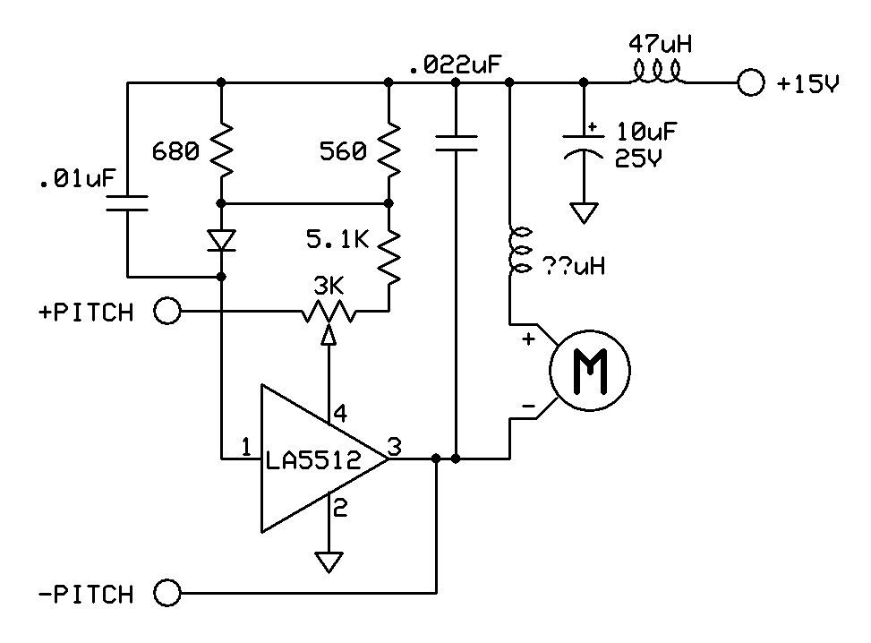
The drawing you have of the triangle symbol.... is a block symbol for an amp, and the pointed end matters because otherwise it confuses things -- the pointed end is supposed to symbolize the flow of the circuit. Additionally, you should draw and number it like on the sample diagram for 1 so that we are consistent with and 2 so we can compare to that other diagram which is all we have for reference. Otherwise it gets so ever confusing. I tried to redraw the diagram so that it becomes easier to compare to the sample circuit, except some things don't seem to jive with what I'm seeing on when I try to visually route the component vs foil side images, vs the diagram you drew.
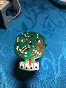
The IC pin enumeration in your original drawing (where p1 is at the notched end) should be right and at first glance, it somewhat matches up to the sample circuit if you mentally ignore that the pointed end is wrong which is good. I wish I had the board in front of me so I can flip, and meter out the traces to compare. But some questions.... the diode in your drawing has one end connected to pin 1 as well as a common point between 2 ceramic caps. But the way I see it, it appears that pin-1 & the diode cathode connects to one of the ceramic caps legs but not at the common point where the 2 caps are tied together like you have it. The common union of those two ceramic caps looks like it is tethered to the big green inductor and one of the resistors. Speaking of which, on your diagram, you show parallel resistors which I presume are the two that are splayed, which I can't see how they are paralled. Also on your board, I count 3 resistors -- 2 the same size, and a smaller one tacked below. However, in your drawing, you only show 2. With these issues, I didn't even bother to continue searching and routing since the angle of the pic of board obscures the edges of some of the traces which makes it unclear where a traces begins and ends. However, please recheck your drawing. It's possible that I am misreading the boards since it's not in front of me but there is enough disparity that concerns me a bit. I suggest you scrap your original drawing and start over using the IC symbol and pin locations consistent with the Sanyo sample circuit diagram.
Look at the pics below. I flipped the PCB foil image (mirror) so that it is easier to picture where the locations of the components would be.

The drawing you have of the triangle symbol.... is a block symbol for an amp, and the pointed end matters because otherwise it confuses things -- the pointed end is supposed to symbolize the flow of the circuit. Additionally, you should draw and number it like on the sample diagram for 1 so that we are consistent with and 2 so we can compare to that other diagram which is all we have for reference. Otherwise it gets so ever confusing. I tried to redraw the diagram so that it becomes easier to compare to the sample circuit, except some things don't seem to jive with what I'm seeing on when I try to visually route the component vs foil side images, vs the diagram you drew.
The IC pin enumeration in your original drawing (where p1 is at the notched end) should be right and at first glance, it somewhat matches up to the sample circuit if you mentally ignore that the pointed end is wrong which is good. I wish I had the board in front of me so I can flip, and meter out the traces to compare. But some questions.... the diode in your drawing has one end connected to pin 1 as well as a common point between 2 ceramic caps. But the way I see it, it appears that pin-1 & the diode cathode connects to one of the ceramic caps legs but not at the common point where the 2 caps are tied together like you have it. The common union of those two ceramic caps looks like it is tethered to the big green inductor and one of the resistors. Speaking of which, on your diagram, you show parallel resistors which I presume are the two that are splayed, which I can't see how they are paralled. Also on your board, I count 3 resistors -- 2 the same size, and a smaller one tacked below. However, in your drawing, you only show 2. With these issues, I didn't even bother to continue searching and routing since the angle of the pic of board obscures the edges of some of the traces which makes it unclear where a traces begins and ends. However, please recheck your drawing. It's possible that I am misreading the boards since it's not in front of me but there is enough disparity that concerns me a bit. I suggest you scrap your original drawing and start over using the IC symbol and pin locations consistent with the Sanyo sample circuit diagram.
Look at the pics below. I flipped the PCB foil image (mirror) so that it is easier to picture where the locations of the components would be.

I'll try to translate to schematic when I get a chance. I also want to ask you what you think about that small resistor tacked on below. Does it appear to be a retrofit adjustment to the circuit? I find it weird that resistors of different types or wattages would be paralleled like that. Typically speaking, when manufacturers design a product and they need a specific value, they get them custom made if they aren't a normal off the shelf value. To parallel a couple of resistors to come up with a value seems doubtful, especially since there are only so many possible values combinations before you need to combine 3 or more to arrive at a weird "critical" value. 560+680 comes up to 307r. 270, 300 and 330 ohm resistors are common values which makes it seem suspicious, especially when there is also a pot in series --somehow seems fishy to me. After all, if 307R was the desired value, I find it unfathomable that 300R would not work. Even 270 or 330 should be acceptable in my opinion. Now on the other hand, if this was an attempt to alter the resistance in order to speed up or slow down the motor as a retrofit attempt, then that scenario does seem plausible. Since no circuit diagram exists for that pcb, it is important that we trust the design or layout in its current condition.
Therefore when you look at it, what are your thoughts ? Does it look "original "?
Therefore when you look at it, what are your thoughts ? Does it look "original "?
It does look original to me due to the way that the solder looks and the fact that I fully believe the motor end "casing" had never been touched/removed before since there were no signs of it. I could be wrong but it doesn't look at all like it has been "messed" with.
Also, there is a hole in the board where that resistor seems to sit which I can only assume is there so that the components needed to go roughly in the same place as each other without taking up too much space. That green "inductor" seems to go in a similar spot on the other side of the board.
I'm 99.9% that the values are correct because when checking them originally I lifted a leg to check their values against their markings.
caution
Member (SA)
baddboybill
Boomus Fidelis
Just wondering why havnt you tried changing the VR in motor? In my opinion its the most common issue with these motors.
Shazam! Caution to the rescue! Thanks Eric, you saved everyone a bunch of work. Btw, can you possibly complete the schematic by adding the resistance network as shown in post #11?
Oh and what drawing program do you use? I like it. Mine draws such narrow skinny lines.
Oh and what drawing program do you use? I like it. Mine draws such narrow skinny lines.
caution
Member (SA)
Bill I think docs bought a new motor speed controller
I use the free schematic tool that expresspcb.com makes their customers capture their designs with.
https://www.expresspcb.com/free-cad-software
I use the free schematic tool that expresspcb.com makes their customers capture their designs with.
https://www.expresspcb.com/free-cad-software
? You mean like an off the shelf pwm controller?caution said:Bill I think docs bought a new motor speed controller
Dave, your board has a 3k pot and the sample Sanyo diagram uses a 50k pot (in the same location). It's true that you have a few more resistors in series but only the (5.1k ??) resistor has any significant resistance to it when compared to the 50k ohm pot indicated in the sample circuit and there is an un-identified resistor R(t) also in series in the sample diagram which might well be represented by one of, or combination of resistors that you also have in yours.
I can't help but wonder whether there is enough resistance to pin 4. I understand that there is still a resistance network externally not accounted for in the sample diagram but it seems to me that the additional external circuitry might even make the motor run faster. In fact, you said youself that with the external circuitry unplugged, it has no effect on the motor speed which tells me it's maxxed out.
In any event, if all the components are in proper working order, then either the motor was swapped out and the incorrect one is in there which is incompatible or the values of the components in there should warrant further examination, especially when they deviate too far from the sample diagrams which in my experience, when IC's are implemented in a design, the choices of the appurtenant components usually mirrors the manufacturers sample diagram very closely. With this in mind, may I suggest that you consider increasing the value of the pot currently installed from the 3k to 50k if nothing else, as an experiment and see if perhaps the circuit then becomes responsive to variations in the pot position. The other reason why I suspect that pot (and not a misapplication motor) is that the internal pot has no effect which should not happen regardless if the correct motor is in there or not. It's worth a try, especially if you have an extra pot on hand to try.
caution
Member (SA)
Dave said he "ordered a LA5512 and will go ahead with that replacement"Superduper said:? You mean like an off the shelf pwm controller?Bill I think docs bought a new motor speed controller

 Well, color me blind. And all this time, I thought that the "new" chip was already installed and it was still doing the same thing. No wonder it's not working right -- the same cast of suspicious characters are still there.
Ok so I wasn't mistaken. Then I reiterate post #112. Try a 50k pot and see if that restores some adjustment in the motor speed.
baddboybill
Boomus Fidelis
Ok i musta missed that in post.caution said:Bill I think docs bought a new motor speed controller
I use the free schematic tool that expresspcb.com makes their customers capture their designs with.
https://www.expresspcb.com/free-cad-software
baddboybill
Boomus Fidelis
- Status
- Not open for further replies.