Amp Upgrade for Sharp VZ-2000

nwalsgrove

New Member
Hi guys, newbie here.

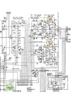
I want to fit a new amp board to drive some woofers in my 2000. The plan is to bypass ic401 and put another board in its place. There is 17v from cnp403 pin 4 (circled in green) powering the amps as it is (orange) so I could intercept this at the top after the nodes (brown strike) so keeping the power feeding to ic402 which I think is powering the tweeters (is this right?). Then splice the speaker feed in to the new amp outputs (purple). The other option would be to bypass both amps and use a crossover, but it's mostly the bass drivers that I'm concerned with. Unless that is particularly easier and more efficient.

Am I in the right ball park here and have I missed something that is going to cause problems or damage? Is it even going to work?

Superduper I'm looking at you!

I've already replaced the drivers and it does sound better, but the amp is not so strong and it could do with more headroomScreenshot 2024-12-22 at 15.46.15 copy.jpg
 

Attachments

  • Screenshot 2024-12-22 at 15.46.15.pdf
    1 MB · Views: 4

caution

Member (SA)
Seems plausible! You might want to make sure the power supply in there can handle the upgrade though.
 

Superduper

Moderator
Staff member
You've circled the L amp for the tweeter and the L amplifier of the woofer (orange circles). You've also identified the L and R Tweeter signal lines (violet slashes) so if you splice into those circuits, you'll only be powering the tweeters with your new amp. You need to better familiarize yourself with the circuits beforehand.

Also, circuit designers will size the power supply and transistor and rectifiers, etc. based on the needs of the amplifier. If you are shoehorning a new and more powerful amplifier in there, it will almost certainly consume more power than the old power supply can provide. You can upgrade it, but be aware that this may turn your VZ into an AC only device, since the D batteries almost certainly won't be able to provide the oomph needed unless you use NiMH or Lithium but then voltages will be off.

And during design of the PCB, the traces are designed to carry a certain amount of current. How much more powerful is your new amp? Just a little or a lot? Because the PCB traces might not be thick enough to carry the juice you require. If you think you can solve this by jumping power with a wire directly, think again... this parallel supply (and maybe ground) supply wiring is almost certainly going to create a ground loop nightmare that will manifest as a hair pulling hum that you may never resolve. If you want to design a special daughterboard that plugs into the main board where the orig extracted original amp IC resided, to tie into all the circuits you need, that may be an option. But again, see the next paragraph regarding SE or BTL amplifiers.

Also, the audio signal traverses the (int/ext) speaker switch, the headphone jack, before it gets to the speakers. If you want to retain those features, you will have to deal with the headphone circuit which is designed for SE amplifiers. If you are installing a more powerful amplifier, then chances are that it will be a BTL design. The difference is that SE designs use a common ground, but BTL designs use a floating ground. Your headphone circuit was designed with the currently installed amplifiers operating in SE mode, and doesn't have the extra ground lead to actually float the headphone drivers. Of course you can simply cut all those other features out and have only your new amp powering the woofers but your boombox will be losing more and more features.

This boombox is Bi-amplified. When the EXT speakers or Headphones are activated, one amplifiers will need to be muted or speakers switched out of circuit. If you are boosting the woofer circuit only, how will you deal with the tweeters which may not be in sync with the SPL of the woofers? Also, if you plan to retain the original muting circuit, you will have to study the muting circuit carefully to see how exactly it works. It's a bit complicated, I suggest you make sure you are prepared for it.

Bottom line is that while in principle, it should be possible, However, the reality is often another story. This is a fairly complicated set, as boomboxes goes.
 

nwalsgrove

New Member
Thanks, this is very useful.

I got the amps the wrong way round...... I think it would be less complicated to cut out both amps and drive all speakers with the new one, and a crossover. I haven't got one yet but I'm looking at some Aiyima tpa3116 modules on aliexpress that want 12-24v. There are various output sizes and I'm thinking they won't be as big as they claim without a lot of distortion so bigger would be better there. A the moment I either use AC or a 5 cell lithium pack bucked down to 15v. The headphone/muting circuit is something I haven't looked much into yet but I don't mind forgetting about it for now and getting back to it at a later date or using a simple switch at first like the ext speakers. Bit worried about what you said about the pcb traces not being big enough. Would this include everything before the power amp? What if it was powered separately? Could I keep most of it as is, cut the power to the old amps and pick up the signal after the bass/treble faders and feed the new amp a separate supply from the same battery pack? I remember you saying somewhere it's a bad idea to pick up the signal from the headphone port
 
Last edited:

nwalsgrove

New Member
You've circled the L amp for the tweeter and the L amplifier of the woofer (orange circles). You've also identified the L and R Tweeter signal lines (violet slashes) so if you splice into those circuits, you'll only be powering the tweeters with your new amp. You need to better familiarize yourself with the circuits beforehand.

Also, circuit designers will size the power supply and transistor and rectifiers, etc. based on the needs of the amplifier. If you are shoehorning a new and more powerful amplifier in there, it will almost certainly consume more power than the old power supply can provide. You can upgrade it, but be aware that this may turn your VZ into an AC only device, since the D batteries almost certainly won't be able to provide the oomph needed unless you use NiMH or Lithium but then voltages will be off.

And during design of the PCB, the traces are designed to carry a certain amount of current. How much more powerful is your new amp? Just a little or a lot? Because the PCB traces might not be thick enough to carry the juice you require. If you think you can solve this by jumping power with a wire directly, think again... this parallel supply (and maybe ground) supply wiring is almost certainly going to create a ground loop nightmare that will manifest as a hair pulling hum that you may never resolve. If you want to design a special daughterboard that plugs into the main board where the orig extracted original amp IC resided, to tie into all the circuits you need, that may be an option. But again, see the next paragraph regarding SE or BTL amplifiers.

Also, the audio signal traverses the (int/ext) speaker switch, the headphone jack, before it gets to the speakers. If you want to retain those features, you will have to deal with the headphone circuit which is designed for SE amplifiers. If you are installing a more powerful amplifier, then chances are that it will be a BTL design. The difference is that SE designs use a common ground, but BTL designs use a floating ground. Your headphone circuit was designed with the currently installed amplifiers operating in SE mode, and doesn't have the extra ground lead to actually float the headphone drivers. Of course you can simply cut all those other features out and have only your new amp powering the woofers but your boombox will be losing more and more features.

This boombox is Bi-amplified. When the EXT speakers or Headphones are activated, one amplifiers will need to be muted or speakers switched out of circuit. If you are boosting the woofer circuit only, how will you deal with the tweeters which may not be in sync with the SPL of the woofers? Also, if you plan to retain the original muting circuit, you will have to study the muting circuit carefully to see how exactly it works. It's a bit complicated, I suggest you make sure you are prepared for it.

Bottom line is that while in principle, it should be possible, However, the reality is often another story. This is a fairly complicated set, as boomboxes goes
 
Last edited:

Superduper

Moderator
Staff member
I haven't got one yet but I'm looking at some Aiyima tpa3116 modules on aliexpress that want 12-24v. ..............Bit worried about what you said about the pcb traces not being big enough. Would this include everything before the power amp?

The VZ2000 specifications state a power consumption of 60 watts. With 15v nominal, that would be 4A and not all of that power is reserved for the amplifier. The amp that you linked to says that for the rated output, it wants 24v/6A. That equals 144 watts. Clearly the internal power supply won't be able to supply nearly that amount. The specifications also states a minimum of 3A or more. It's clear from those numbers that the best you can expect from this new amp with the internal supply will be whatever the minimum output rating for that amp. It may not even sound any better than the factory amp if underpowered. Your best bet is to use a separate laptop power supply as suggested by the description. You may either have to install a separate DC jack for the power, or see if you have enough internal room to shoehorn that in there. For obvious reasons, this will then become an AC only device. By bypassing the internal amp, the machine won't work on DC anymore. However by using a completely separate power supply, you will likely avoid any ground loop hum issues.

As for your questions regarding circuit traces, member Caution is probably better suited to answer that question. But during circuit board design, the trace width is always taken into consideration based on the needs for that portion of the circuit. Circuits that need less power will have narrower traces and circuits that need more power will have wider traces. The width of the trace will determine how much current it can supply. Engineers design these traces based on the anticipated current needs of the project. You are modifying that circuit so the needs are going to change drastically. Whether there is sufficient safety margin built in with the orig design is unclear. This is a 40+ year old device after all. However, there is a limit to how fat a trace can be designed because circuit boards are usually quite busy and there usually isn't enough room to make all fat traces. If you were to design a new circuit board today, the software actually allows you to modify the trace widths based on the amount of expected current (power vs signal traces). However, 40, 50 years ago, there was no such thing as software and these PCB were probably designed by hand.
 

caution

Member (SA)
Trace width isn't an issue because you're not trying to drive the existing circuitry harder, just need a beefier power supply for the new amp.
 

Superduper

Moderator
Staff member
In the initial post, the OP intimated that he was going to try to tie into the area on the schematic indicated with the brown slash. That would be on the main pcb so traces would be involved at that location. However, he could possibly tie into the pads under the connector itself to bypass the traces I suppose and render the PCB traces on the main board irrelevant. However, connector CNP403 is on the main circuit board so that harness will have to carry the current he needs from the PS board. If his new amp alone wants 144 watts, at 15V, that would be just about 10A, which is really stretching it for those harness wires which are probably 20 gauge max? Add another 5 to 10 watts for the rest of the overhead needed to run the boombox and it's gonna be over 10A. Obviously, the factory transformer won't output nearly that much VA, unless he installs a beefier transformer. And rectifier. And filter caps. etc.
 

caution

Member (SA)
You could have the original power supply continue to run everything except the new amp, which has its own laptop power supply or whatever, if only sharing AC is adequate, but even cutting out the old supply is fine because the new amp module is the only thing that needs excessive current, and that should tie directly to the (new)power supply. Nothing on the original boards need to draw extra current
 
Last edited:

nwalsgrove

New Member
Having put the machine back together to hear the new woofers and tweeters properly, I'm not sure it can really be much improved on. It is so much better now I'm really enjoying it with its original amp. I even made myself some resistors to attenuate the tweeters but removed them in the end because when it was back together it turned out they weren't needed, the balance is lovely.

I was given some really good advice once when buying some speakers, the guy told me to upgrade hifi gradually in stages so you can enjoy each one properly before going to the next. If for your first car you buy the best car in the world ever you're never going to top it and when the novelty wears off you'll never get it back.

Bottom line is that with some better drivers, styli and a rechargeable battery this machine has just had a huge upgrade and is my go to player (for now). I don't think the box could handle any more power as it might shake itself apart, the bass won't go any deeper in those little enclosures. The plastic is so old and brittle I'm scared to work on it much more. Maybe a full re-cap one day but that's a bit further down the line I think
 

Superduper

Moderator
Staff member
There definitely is an allure to having more power, which in a separates type system, is ideal. But in an all in one solution such as the VZ-2000, especially with it having a built in turntable, there really is a limit to how much internal power you can run before you run into issues with feedback and skipping. I didn't bring this up because I presumed that you had already considered this. Since it was already suggested that doing the amp and laptop power supply thing may render the unit an AC only machine, you might as well just have the line-out jacks run to an external amplifier powering external speakers that won't transmit the vibrations to the turntable. At 37 pounds, it's really not something one would carry around anyhow. And you only need to tether a single stereo RCA cable and you're off to the races. There are other boombox models that are not nearly as fragile and heavy as this one is, and those are probably better suited for doing the big a** amp speaker and amp thing.

You could have the original power supply continue to run everything except the new amp, which has its own laptop power supply or whatever, if only sharing AC is adequate, but even cutting out the old supply is fine because the new amp module is the only thing that needs excessive current, and that should tie directly to the (new)power supply. Nothing on the original boards need to draw extra current
Have you taken a look at the VZ power supply circuit? It's not the typical simple PS, in addition to all the standard PS components, there are also at least a half dozen transistors along with the standard caps and resistors and diodes appurtenant to those circuits, and there are multiple outputs. Yes, it's possible to cut out the original power supply, but only the transformer and rectifier portion. The remainder needs to be retained so the best location to tie into it would be to remove the original bridge rectifier and supply new input to the where the rectified output areas are. However, the boombox circuits had 4 amperes reserved for it (less by some amount depending on how much the original amps would draw without a load if they are just going along for the ride). That would require a pretty big laptop supply in order to supply enough for the new amp, AND power the original circuitry too. However, seeing that the laptop supply needs to be plugged in anyhow, there's probably no benefit to cutting out the orig supply.
 

nwalsgrove

New Member
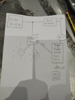
How about this approach? At the moment it is powered by a 5 cell lithium pack through a buck converter to bring it down to a constant 15v, which works wonderfully and the battery lasts so well I can't seem to run it down. If I take a parallel feed from it before the buck converter I can power the new amp directly from the battery and it will be getting 21v on full charge and 15v on empty. Then take the audio signal before it reaches the old amp and run it to the new one (wxy). Then passive crossover then speakers. Unit gets constant 15v and amp gets as much as the battery has to give. These amp modules normally ask for 12v-24v then they will draw more current as the battery charge decreases

17354790722247852678695118208105.jpg
 

Superduper

Moderator
Staff member
You said you already have the amp and that it's hooked up to a battery pack, I guess you can just try it and see, maybe cross your fingers

In my opinion and experience, that setup you have drawn is ripe for a potential ground loop issue. To better illustrate, picture your tone/etc. block and that wxy wire. Imagine that electrons flow from a power source (battery pack) to that tone/etc block, and then from there, the + and - signal wires goes to the amplifier. In an ideal situation, the (+) signal will go to the new amp, with the return path first going back to the (-) of the tone/etc block before going back to the buck converter and then finally to the battery pack.

However, in your situation, your amp is powered directly from the battery pack and everything else is powered through the buck converter. This wouldn't be a problem when both the old and new amp work independently. (new amp taking input from an external mp4 device, etc, old amp audio signal it's own internal source). However, once you tether the new amp and the old tone circuit, now possibly with a different ground potential through that audio cable, you have a potential for the (-) path to travel directly back to the battery pack bypassing the tone/etc. block from which it came. Or some of the signal going back to the battery path, and some going back through the tone amp, buck converter before hitting the battery pack. In either situation, alternate ground paths is going to create a hum. If your buck converter doesn't utilize a common ground, then a difference in ground potential is almost 100% guaranteed.

Since a lot of this depends upon how much of a ground potential difference in introduced by the audio signal taking a shortcut path directly to the battery pack instead of the normal path back through the tone amp, it's unclear whether there will be an issue. Too many variables, leads length, etc. You'll just need to try and see.
 

nwalsgrove

New Member
I will try it one day, for now I'm just enjoying the new cones and tweeters. I'm not sure it can be improved on much more now because on full volume, it doesn't distort but it does feed back through the turntable (depending on the music) but I don't want it on full anyway. I think now it might benefit more from some good eqing, or maybe I'm already pushing it as far as it can go? I'll get back inside it one day when I know exactly what I want to do
 

Reli

Boomus Fidelis
The VZ-3000 and 3500 have way more power, so you might consider getting one of those. They're indoor-only models, but they still have the same linear turntable nostalgia.
 
  • Like
Reactions: BoomboxLover48