No luck, same results. Grrrr.......... Ok guess we got multiple issues once again here. It's almost to be expected, why should things start getting easier now, lol. Break out the fluke meter again.
The Saga Continues (blu_fuz 5350)
- Thread starter Superduper
- Start date
- Status
- Not open for further replies.
Ok, moving on.......
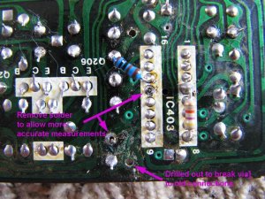
Firstly, some measurements were inconclusive. On the tuner board, installed an IC socket for IC2 which allowed me to easily remove the IC from the circuit whenever I needed to so I could take more accurate measurements without the internal circuitry of the chip skewing the measurements. In this case, I did not want to remove the IC since this is a much more simpler circuit than the tuner itself. I basically just removed the solder from the pads to isolate the pins on those pads I wanted to test. After taking measurements I could trust, I proceeded accordingly.
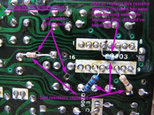
Here are the "fixes" to get Stereo adjustment working again. Note that there is one resistor that Joe installed (see previous photos, resistor installed between pins 4 & 8). I had to replace that resistor because for some reason, Joe had installed the wrong resistor. The resistor installed was a 47k ohm resistor, when the schematic called for a 4.7k ohm resistor. That's 47,000 installed when it should have been 4,700 ohms. This is why we should never "presume" anything, although admittedly, I ignored and didn't previously test that part of the circuit because I knew that Joe already fixed it. Ok, what's an extra zero, right? BTW, while you can see that the new resistor only bridged pins 4-6, that's perfectly fine since pins 6-8 are connected and I did verify that they are indeed connected. With the new resistor having a smaller physical body, I didn't want to stretch it any more than necessary.
Note: you can actually see some corossion forming near pin 9 of the IC. Luckily copper is more durable than the conductive material used to print the top traces & resistors.
I've checked and rechecked, all looks good. So I'm pretty confident that this is going to fix stereo. Hopefully, the MPX decoder chip itself is OK because I don't have one of those in stock. Be back later after some reassembly, some finger crossing, etc. etc.
Firstly, some measurements were inconclusive. On the tuner board, installed an IC socket for IC2 which allowed me to easily remove the IC from the circuit whenever I needed to so I could take more accurate measurements without the internal circuitry of the chip skewing the measurements. In this case, I did not want to remove the IC since this is a much more simpler circuit than the tuner itself. I basically just removed the solder from the pads to isolate the pins on those pads I wanted to test. After taking measurements I could trust, I proceeded accordingly.
Here are the "fixes" to get Stereo adjustment working again. Note that there is one resistor that Joe installed (see previous photos, resistor installed between pins 4 & 8). I had to replace that resistor because for some reason, Joe had installed the wrong resistor. The resistor installed was a 47k ohm resistor, when the schematic called for a 4.7k ohm resistor. That's 47,000 installed when it should have been 4,700 ohms. This is why we should never "presume" anything, although admittedly, I ignored and didn't previously test that part of the circuit because I knew that Joe already fixed it. Ok, what's an extra zero, right?
BTW, while you can see that the new resistor only bridged pins 4-6, that's perfectly fine since pins 6-8 are connected and I did verify that they are indeed connected. With the new resistor having a smaller physical body, I didn't want to stretch it any more than necessary.Note: you can actually see some corossion forming near pin 9 of the IC. Luckily copper is more durable than the conductive material used to print the top traces & resistors.
I've checked and rechecked, all looks good. So I'm pretty confident that this is going to fix stereo. Hopefully, the MPX decoder chip itself is OK because I don't have one of those in stock. Be back later after some reassembly, some finger crossing, etc. etc.
Ok, so a picture(s) says a thousand words.
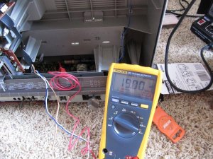
First image. Proof is in the pudding. Now, was able to adjust the pilot signal to a rock steady 19khz. The test point is the pigtail wire behind the MPX decoder chip. Strip enough to attach a retractible spring hook probe to it, and set your meter to AC frequency counter setting. Adjust the adjustment pot until reading stabilizes at (or as close to as possible), 19khz.
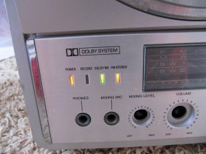
Ok, this image should put a smile to Joe's Face. No words need to describe, picture says it all:
OK, that's it for today. TOMORROW, we will see what's up with the AM and SW bands and focus on those parts of the tuner circuitry, because right now, it's really weird as those bands only plays one song (in every station), over and over again, "The Sounds of Silence." Literally.
First image. Proof is in the pudding. Now, was able to adjust the pilot signal to a rock steady 19khz. The test point is the pigtail wire behind the MPX decoder chip. Strip enough to attach a retractible spring hook probe to it, and set your meter to AC frequency counter setting. Adjust the adjustment pot until reading stabilizes at (or as close to as possible), 19khz.
Ok, this image should put a smile to Joe's Face. No words need to describe, picture says it all:
OK, that's it for today. TOMORROW, we will see what's up with the AM and SW bands and focus on those parts of the tuner circuitry, because right now, it's really weird as those bands only plays one song (in every station), over and over again, "The Sounds of Silence." Literally.
Oh and note my very cool makeshift electronics repair workstation, complete with shaggy work surface.
Wow.
I installed the wrong resistor!?!?! How the f'k did that happen!?!? Hahaha, sorry bud. I wasn't trying to make it worse.
Proof is really in the picture. Full FM functions, now I really can't ask for more. Great job Norm and your workstation looks like mine did.
I installed the wrong resistor!?!?! How the f'k did that happen!?!? Hahaha, sorry bud. I wasn't trying to make it worse.
Proof is really in the picture. Full FM functions, now I really can't ask for more. Great job Norm and your workstation looks like mine did.


It's no problem Joe. To be honest, I recheck my own work often just to make sure I didn't screw up. I've messed up more than once. We are all human after all, so the lesson to be learned here is presume nothing, check everything.blu_fuz said:Wow.
I installed the wrong resistor!?!?! How the f'k did that happen!?!? Hahaha, sorry bud.
TIP: In case anyone is wondering why keep stopping and rechecking results without first checking and fixing ALL the faults first...... the thing is, what is everything?
Anyhow, for several reasons. #1, the checks, repairs, and retest verificiations was performed on but a miniscule part of the entire circuitry. We are trying to solve a problem, nothing more, nothing less. We are not doing a body off car restoration where every part is checked, replaced, spit and polished. So if the "fix" really is a fix, then that issue is resolved and we can move on. Additional checking and verifying could take forever if we have to desolder pads, and trace every connection and component on the board. Secondly, sometimes moving too far ahead means that if the results aren't what we expected, and then we need to recheck our work, then going back and rechecking many layers of repairs is going to be a nightmare since the traces on the board diagrams no longer match. So going slow and checking along the way with each steps ensures that if we make a mistake, it is easy to undo that. Example -- if a voltage measurement is off and we did a repair that we expects should correct that voltage disparity, but instead it is the same or worse, then we know we need to recheck our work. But if we did 20 steps and found that voltage measurements are now all over the map, where did we go wrong? Anyhow, this is just a tip for you adventurous hackers.
Norm, I'm sure you've heard this before, but it's great you explain this stuff in such detail. While a lot of it is confusing and hard to understand at first for some of us, after reading over it a few times it becomes more clear, and helps me/us learn.
Most the time I read this stuff to learn, it's not even about the box, but this I know is one of the great boxes, so it's even that much more interesting. Im trying to avoid all the encouragement posts, just saying you da man!
Most the time I read this stuff to learn, it's not even about the box, but this I know is one of the great boxes, so it's even that much more interesting. Im trying to avoid all the encouragement posts, just saying you da man!
Hell of a thread

You are wearing anti-static gloves and have an anti-static wristband properly grounded right?Superduper said:Oh and note my very cool makeshift electronics repair workstation, complete with shaggy work surface.
RX 5350 got one of the most sensitive radios you can find. FM fixing alone is a Great Jump here! 
I want to hug my 5350 again and again!
I want to hug my 5350 again and again!
Ok, did my tests and measurements on the AM/SW sections. For those of you that do not know, AM and SW sections are almost always related so the failure of one band often means no SW too. Aside from the AM ferrite tuning coil, there are 6 other transformer coils for the AM section, and some capacitors, resistors. No active components (aside from IC2, which handles all of the AM functions internally. Because of voltage check points and specs data are usually only given for active components, I have performed resistance tests almost exclusively while diagnosing this portion of the tuner circuit.
I won't bother to give a blow by blow on this section since the thread is starting to get long and maybe boring for those not really into the technical aspects of the repair, so I'll just say that I've found several failed resistors and faults throughout the circuitry traces, the cumulative total of which affects ALL 6 of the coils either directly or indirectly. Suffice it to say that it's no wonder AM and SW is not working. Except for 1 of the 3 affected bands, none of the RF signals were being passed to IC2. Worse is that the power rails for those bands is blanked too.
Going to spend the afternoon getting those corrected, and then cross fingers. Joe and I agreed that if at any point of the diagnosis or repair, further progress requires using an oscilloscope or RF generator to proceed, then for me to stop since I don't have any of my heavy equipment available to me, as they are all still in storage from my 1900 mile move last year. Heck, I'm lucky just to have found what I have. (I even had to purchase more solder since I can't find my stash, but now I have too much -- anyone want to buy some? lol).
Question:
What would cause all these resisters through out to be popped?
Over voltage?
Storage in bad environment?
What would cause all these resisters through out to be popped?
Over voltage?
Storage in bad environment?
Chris, check out the image below. They will give you an idea of what we are dealing with. Because I have been mostly showing photos of the repairs (bottom, foil side), it might be hard to picture exactly what it is that is being replaced or repaired.Lasonic TRC-920 said:Question:
What would cause all these resisters through out to be popped?
Over voltage?
Storage in bad environment?
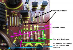
This is the side that is actually being repaired. I have shown you some sample printed traces and resistors. At some point, all of these traces route underneath by way of a VIA (it looks like a circular pad) and that is where the repairs will be performed. The reason why is that the printed material is not solderable. Also, as it's pretty cluttered above and many traces route under components (see the trace below the row of discrete resistors), it's not really practical to try to make a repair topside, even if one would want to use conductive paint to attempt a repair.
As for why these traces go bad, it's usually environmental. Anyone that has ever disassembled a pot would recognize the carbon traces that are similar to those printed traces. As we know, carbon has resistance but the resistance varies depending upon the thickness of the carbon. Anyone with an old-school automotive background has used a carbon pile battery load tester. Same thing. So the resistance of the traces and resistors can be tailored simply by varying the thickness. The thicker the coating, the lower the resistance. Usually, the entire board is then conformal coated (clear protective coating). If corossion sets in due to maybe degraded conformal coating and perhaps accelerated by the introduction of salt (near ocean?) or acidic liquid (cola, coffee), then the printed material is compromised. These printed features usually begin changing in resistance, almost always increasing, until you have an open circuit.
Hope this explains and makes this repair exercise easier to understand.
So the tunnels are used, to repair from one side of the board to the other, otherwise you'd have to run wire all the way around the board as the only other method. That's what I think I'm understanding.
Got it...well, it seems like your making head way. This is great information and I have done similar things.
The repair you made to the power input and running external jumpers...yep, done that.
This is certainly a radio worth saving, so I give it two thumbs up
The repair you made to the power input and running external jumpers...yep, done that.
This is certainly a radio worth saving, so I give it two thumbs up
No, the tunnels are called vias. They exist for the sole purpose of connecting the top (printed traces) to the bottom copper traces. When the top traces deteriorate but have not completely failed, I will sometimes cut them out of circuit by drilling out the vias. This breaks the connection and takes the deteriorating circuit path out of the equation, otherwise they will be a parallel path and make the new electrical repaired path have the wrong electrical characteristics. Think of this circuit board as a 3-dimensional one, and the top and bottom sides as being different planes. They are connected by the vias.trippy1313 said:So the tunnels are used, to repair from one side of the board to the other, otherwise you'd have to run wire all the way around the board as the only other method. That's what I think I'm understanding.
The repairs have nothing to do with the tunnels per se, only that repairs MUST be performed ONLY from the bottom side and not the top, once again because ONLY the bottom side can be soldered. Basically while following a circuit trace, the path can squiggle around the bottom, flip to the top side, route around a bit, and then head back down to the bottom side. It can get confusing fast.
So in effect, the top side is what's failing. If a portion has completely failed, we need to duplicate the top circut by fabricating it on the bottom side. If a portion of the top circuit has partially failed, then once again, we need to fabricate a replacement circuit on the bottom side but also, isolate the top circitry so that it cannot affect the new replacement circuit below. Get it?
I still don't know why National engineers went for these printed resistors on the PC board to make things more complicated. I believe they were all small values.
- Status
- Not open for further replies.