Sony FH909 amp common fault?

docs

Member (SA)
Jun 26, 2010
2,558
381
83
52
United Kingdom
Thanks Reno, I’ve been using it already.
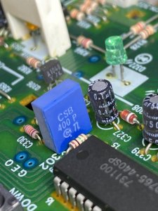
The 2 resistors seem to be ok, I guess I need to see if I can figure out how to test x302.
 

Radio raheem

Member (SA)
May 13, 2009
4,970
920
113
uk
can you bypass the black relay Dave if you haven't already done so lad, it's the sealed one bro, i still suspect that as im not sure what else it can be for
 

docs

Member (SA)
Jun 26, 2010
2,558
381
83
52
United Kingdom
I think the black relay is good Reno, it seems to power up and functions. I've taken a look at it inside and can see it is super clean and there is good continuity across the pins.
I will need to dismantle the unit further to get at the front side of the board where the front fascia is covering. Since the resistors are good round x302, I'm hoping that x302 has markings on it to ID it.

IMG_0981.jpeg
 

Radio raheem

Member (SA)
May 13, 2009
4,970
920
113
uk
ok desolder one of the black relay pins Dave and let me know id love to know what it is for, just humour me lad lol

but if you know what it is for, please tell me lad
 

docs

Member (SA)
Jun 26, 2010
2,558
381
83
52
United Kingdom
That black relay is in the initial power circuit and connects through a transistor to one of the IC's so I'm assuming it is part of the initial standby to power up operation.
 

Radio raheem

Member (SA)
May 13, 2009
4,970
920
113
uk
by pass it if you have no other options lad, the other relay was so marginal on on mine a meter couldn't tell, i told the guy to replace it and it fixed the problem, i'll leave it to you buddy as the last thing i want to be is a pain in the A$$ lol :-)
 

docs

Member (SA)
Jun 26, 2010
2,558
381
83
52
United Kingdom
Rimmer36 said:
Dave are you still up for buying boxes lol
In this current climate I won’t be doing anything because of all the uncertainty.

Norm, Is there any way to test the circuit with a jumper or such to see if the unit works in this instance?
I’ve bought a couple of CSB400P’s but they’ll take a while to arrive.
Checked my dmm, it has a 2M and 200m ohm option.

Well I answered my own question, by reversing the oscillator, as it isn’t polarised, and doing a quick on/off test a dozen times, the unit turned on successfully almost every time. It seems to need an initial power up then it will mostly be in favour of powering on properly. That part is still not quite right so i’ll replace it anyway but I think we have a winner!
 

Radio raheem

Member (SA)
May 13, 2009
4,970
920
113
uk
that is great news Dave on the fix....id probably regret selling my radios anyway mate, stay well lad
 

Superduper

Member (SA)
docs said:
Norm, Is there any way to test the circuit with a jumper or such to see if the unit works in this instance?

Checked my dmm, it has a 2M and 200m ohm option.
1. Not that I know of. You must not be understanding how MPUs work. Because if the set is stalled because the microcomputer(s) lost their clock signal, there is no single jumper is going to reboot the system(s). Each MPU might have a reset pin. If that's the case, you might be able to pull that pin high or low (depending on what the datasheet says), which might be able to reset it but it will only work if the oscillator is putting out the clock signal.

2. I don't know what that means. Did your meter have at least 20mΩ input impedance when you probed pin 20? If not, you probably loaded the circuit and killed the clock signal.