Operation Sanyo M9998!

Status
Not open for further replies.

BoomboxLover48

Member (SA)
Dec 3, 2010
5,762
275
83
Chicago, IL
superlew said:
Nice work Royce! :thumbsup:

I was thinking along the lines of Norm's suggestion but, having never seen or worked on one, I didn't want to give a bad tip.
I've missed or mis-aligned a million pin connectors over the last several years. Of course, they've all been corrected. :lol:
Thanks Arom!

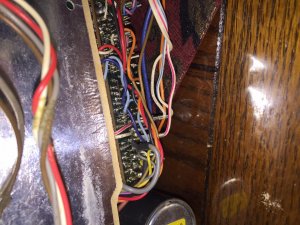
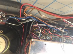
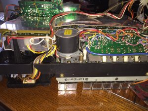
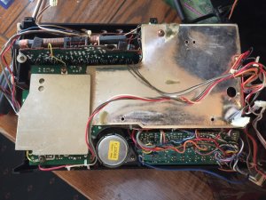
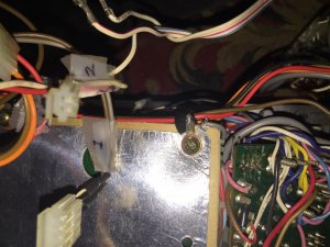
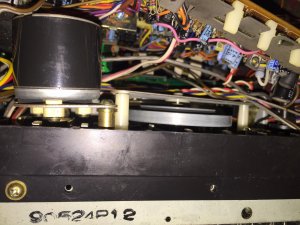
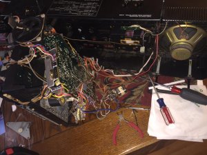
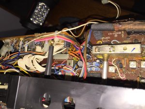
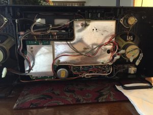
This unit has so many connectors and few ribbon lines also. I was very careful not to flex those ribbon lines which are prone to damage. Once you disconnect the connectors a few times it becomes so easy to know where it all belongs. I numbered them from left to right using tape, also took pics. I saw this main lead connector from amp board to tuner board only when I lifted the main board. I then made sure it was there when I put is back. My bad! :bang:

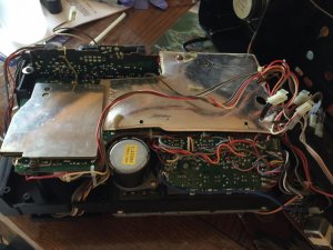
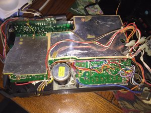
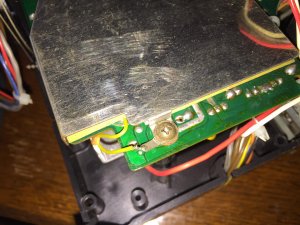
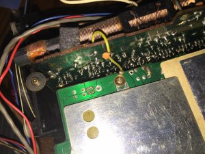
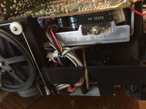
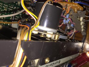
Next time push that connector mounted on both boards, hold it in position, and put the top screw for the board. Then the lower screws to hold the main PC board of the amp.

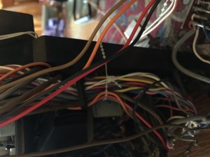
For some reason wires came in the way and I might have accidentally lifted the board only to disconnect it. It doesn't take much to disconnect the line to the tone board.

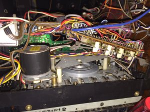
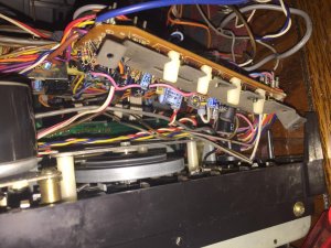
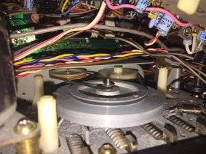
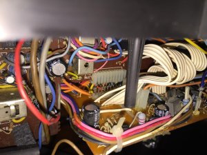
This was a good learning experience! There is no need to remove soldered connections at all. One can easily replace belts from the lower section by lifting the main amp board and use foam pieces in a ziplock bag as a wedge.


Fatdog said:
Super yay!! :clap:
Thanks Bobby! Lessons learned from mistakes!
I am glad we have very helpful members here. :bow: :bow:
 

BoomboxLover48

Member (SA)
Dec 3, 2010
5,762
275
83
Chicago, IL
Here are some pics....

Take pictures as you disassemble.

Disconnect power cord. Remove all the knobs from the front. Open the cassette door, leave it open.

Remove all the back cover screws. Two are hidden in the cassette compartment.
Gently pull out the rear cover because there are several connectors and wire pins to remove.

Looking from the top take pictures of these connectors and mark them.

Antenna connectors and two yellow wire connectors can be easily pulled out holding on the PC board.
On the top right corner you can see the speaker wire 4 pin connector, unplug it.

Once all the connectors from the rear cover top area is removed , lay the rear cover on it's back.

The power lead 4 pin connector goes to the right bottom corner, unplug it.
Now the rear cover can be separated from the front.
Now we are ready for the chassis removal.
On the right side under the speaker a small PC board needs to be removed before taking the chassis out.
Lift the top push buttons and rotate one clockwise and the other anti clockwise, they will stay up locked in a slot. This step is very important or else will break the switches.
Chassis mounting screws can be seen along the rim of the chassis. Once they are all removed chassis will come out easily. Take care not to hold any area of it where the tuning cord is running, also on the tuning wheel gang assembly.
By moving wires around it it can be positioned on a micro fiber cloth buttons and dial plate facing down.
Now start working on partially moving/separating the main board up to get access for belt replacement.

The PC board with cassette controls next to the motor is mounted on a steel plate. This plate is mounted on the metal frame with two small screws. It is a bit of struggle to find the right Philips screw driver tip to unscrew them.

There are white plastic pin tips on the head of the cassette function switches. These plastic tips will fall backwards. There tips need to be re positioned before putting it back.
Before one removes the mounting screws of the mail amp board this cassette control board has to be removed from the metal chassis.
There are several plastic ties securing wire bundles on the side of the main amp board. Untie them before lifting the board slightly up. Lift the main PC board gently and separate like 3 inches.
Use a foam wedge to keep it separated to gain access to the cassette flywheel cover area.
The lower sections of the deck are is now clearly visible.
Two screws hold the flywheel cover. The flywheel cover can be easily removed, but watch the belt guide on it. The new belt has to channel through that cut section on the side of the flywheel cover.
There are altogether 3 belts there to replace. The smallest square belt goes from the small axis pulley of the flywheel to a small plastic pulley. The main flat belt goes from the motor pulley to the flywheel. The other belt connects the middle part of the flywheel to another almost same size plastic pulley.
It is a little tricky to get these belts in position starting with the main flat belt. I used plastic tools to put those belts in place.
Counter small square belt is ~8.0”
I will post belt sizes later.

I have more...
 

Attachments

caution

Member (SA)
Mar 25, 2014
2,509
344
83
Boomboxery
Congrats on bringing this back from the dead! :clap: I knew you would take lots of notes, even then you can miss something.
On complex innards like this one it's so important to write down a note every time you unplug/remove something.
Can't wait to see it back together!
 

BoomboxLover48

Member (SA)
Dec 3, 2010
5,762
275
83
Chicago, IL
baddboybill said:
Awesome!!! It's so great when a big issue actually is only something small ;-)
Exactly! Thanks Bill!

Now I have lots and lots of additional pictures to share if another member needs help.


Now I noticed that the dishonest seller didn't say anything about one bad speaker and missing reel drive axle tips (cogs). Yuck!

I need to find the reel tips and also a speaker for this M9998.
 

Attachments

BoomboxLover48

Member (SA)
Dec 3, 2010
5,762
275
83
Chicago, IL
The reel axle (cog) missing is a big issue!

I just saw this nice thread.

https://boomboxery.com/forum/index.php/topic/22322-repair-reel-table-assembly/

caution said:
Congrats on bringing this back from the dead! :clap: I knew you would take lots of notes, even then you can miss something.
On complex innards like this one it's so important to write down a note every time you unplug/remove something.
Can't wait to see it back together!
Hi Eric, It was a good learning experience!

Now I have to design a cog that can snug fit on the drive axles.

I will come up with a solution to it.
 

T-STER

Member (SA)
Jul 14, 2014
2,246
73
48
UK
BoomboxLover48 said:
The reel axle (cog) missing is a big issue!

I just saw this nice thread.

https://boomboxery.com/forum/index.php/topic/22322-repair-reel-table-assembly/
I had the same issue mate, I ended up taking the spindles from an Aiwa 950 parts box i had (the deck was long since fubar) as they were incredibly similar and in great shape, plays perfect.

I keep decks from any parts box i find and buy them in any shape at bootsales just for aerials/decks/buttons etc so i have quite a spares box, if you have any trouble finding them let me know, i'll compare my spares to my 9998 and find a suitable set and send em to you.
 

BoomboxLover48

Member (SA)
Dec 3, 2010
5,762
275
83
Chicago, IL
Hisrudeness said:
Well done Royce.
Sounds like you're almost there..
Hi Rudy, Couple more things to do.

1. I need to replace one speaker
2. The cog for the take up reel axle and supply reel axle is missing. James fixed it with a Panny part replacement. I am looking for those.
3. I need a record key that was found broken.

I have another box that is also missing #1 & #2, but the rest is in mint condition.

Reli said:
Excellent thread!
Thanks Reli!

If another member needs more pictures, I have more.
 

BoomboxLover48

Member (SA)
Dec 3, 2010
5,762
275
83
Chicago, IL
MyOhMy said:
As much as I like this box I do have a question that's starting to play on my mind somewhat: Is this particular box the complex nightmare to work on it looks to be?
Christine, Instead of making a bigger PC board that can utilize the length and height of the box, the designers left the speaker compartment nearly empty and filled up the middle compartment with layers of PC boards completely covering the cassette section.

So one can see only the rear of the motor and nothing else from the back.

To answer your question I can say after some explorations to the unknown territory and taking pictures, belt replacement is not that hard as I expected.

One has to be extra careful in the disassembly process. The top two buttons cane be damaged if it is not pulled up, turned and locked in place. It is easy to break the tuner chord pulley posts and gang wheel. Ribbon wires can get damaged if one is not careful.

When the chassis goes in the front face of the box always keep an eye on aligning the counter reset button. It can get easily stuck without coming out of the hole. If that is the case the lower part of the chassis won't fit well. Never hold on to the handle because it can easily slide out from the slots.


Belt replacement is the only thing I did after some struggle and hiccups. Now it all became so easy for me to dismantle it and put it all back together.

One would would easily fall in love with the sound quality of this box. A little giant in every way!
 

Attachments

MyOhMy

Member (SA)
Jul 26, 2015
2,509
7
0
71
Sleaford, Lincolnshire, UK.
BoomboxLover48 said:
As much as I like this box I do have a question that's starting to play on my mind somewhat: Is this particular box the complex nightmare to work on it looks to be?
Christine, Instead of making a bigger PC board that can utilize the length and height of the box, the designers left the speaker compartment nearly empty and filled up the middle compartment with layers of PC boards completely covering the cassette section.

So one can see only the rear of the motor and nothing else from the back.

To answer your question I can say after some explorations to the unknown territory and taking pictures, belt replacement is not that hard as I expected. One has to be extra careful in the disassembly process. The top two buttons cane be damaged if it is not pulled up, turned and locked in place. It is easy to break the tuner chord pulley posts and gang wheel. Ribbon wires can get damaged if one is not careful. Belt replacement is the only thing I did after some struggle and hiccups. Now it all became so easy for me to dismantle it and put it all back together.

If you listen to this box one would fall in love with it.
Many thanks for this very informative answer. :yes: The first sentence resulted in perfect clarity to me, once I understood the layout of the boards the mental pictures fell into place so now I can re-read the thread with a little more understanding. I've wanted to acquire one of these for some time so I'll revisit your comments should I ever find myself rollin' my sleeves up for one of these. :yes: :thumbsup:
 

BoomboxLover48

Member (SA)
Dec 3, 2010
5,762
275
83
Chicago, IL
T-STER said:
The reel axle (cog) missing is a big issue!

I just saw this nice thread.

https://boomboxery.com/forum/index.php/topic/22322-repair-reel-table-assembly/
I had the same issue mate, I ended up taking the spindles from an Aiwa 950 parts box i had (the deck was long since fubar) as they were incredibly similar and in great shape, plays perfect.

I keep decks from any parts box i find and buy them in any shape at bootsales just for aerials/decks/buttons etc so i have quite a spares box, if you have any trouble finding them let me know, i'll compare my spares to my 9998 and find a suitable set and send em to you.
Hi T-Ster, Thanks! If you find a pair please PM me. Two would be nice for the time being but need two more for my other M9998. I checked it today and that one is also missing the cogs.


MyOhMy said:
As much as I like this box I do have a question that's starting to play on my mind somewhat: Is this particular box the complex nightmare to work on it looks to be?
Christine, Instead of making a bigger PC board that can utilize the length and height of the box, the designers left the speaker compartment nearly empty and filled up the middle compartment with layers of PC boards completely covering the cassette section.

So one can see only the rear of the motor and nothing else from the back.

To answer your question I can say after some explorations to the unknown territory and taking pictures, belt replacement is not that hard as I expected.

One has to be extra careful in the disassembly process. The top two buttons cane be damaged if it is not pulled up, turned and locked in place. It is easy to break the tuner chord pulley posts and gang wheel. Ribbon wires can get damaged if one is not careful.

When the chassis goes in the front face of the box always keep an eye on aligning the counter reset button. It can get easily stuck without coming out of the hole. If that is the case the lower part of the chassis won't fit well. Never hold on to the handle because it can easily slide out from the slots.


Belt replacement is the only thing I did after some struggle and hiccups. Now it all became so easy for me to dismantle it and put it all back together.

One would would easily fall in love with the sound quality of this box. A little giant in every way!
Many thanks for this very informative answer. :yes: The first sentence resulted in perfect clarity to me, once I understood the layout of the boards the mental pictures fell into place so now I can re-read the thread with a little more understanding. I've wanted to acquire one of these for some time so I'll revisit your comments should I ever find myself rollin' my sleeves up for one of these. :yes: :thumbsup:


I added more information in that section.
 

BoomboxLover48

Member (SA)
Dec 3, 2010
5,762
275
83
Chicago, IL
jimmyjimmy19702010 -James send me the tips and key from AU!

Thank you James! :bow: :bow: :bow:


No more fear to replace belts on an M9998!

I can do it in my sleep. hahaha! :lol: :lol: :lol: :lol:
 

markoneswift

Member (SA)
Dec 11, 2015
295
2
16
Aotearoa New Zealand
Man I had forgotten how tight everything is inside that model. Mine gave up on me and no end of troubleshooting could bring it back. Ended up taking it to the dump, in pieces. A sad day !
 

MyOhMy

Member (SA)
Jul 26, 2015
2,509
7
0
71
Sleaford, Lincolnshire, UK.
markoneswift said:
Man I had forgotten how tight everything is inside that model. Mine gave up on me and no end of troubleshooting could bring it back. Ended up taking it to the dump, in pieces. A sad day !
Did you consider saving it, or at least parts of it, as a donor box? I've seen a few of these for sale that require a resto and/or have missing parts.
 

markoneswift

Member (SA)
Dec 11, 2015
295
2
16
Aotearoa New Zealand
MyOhMy said:
Man I had forgotten how tight everything is inside that model. Mine gave up on me and no end of troubleshooting could bring it back. Ended up taking it to the dump, in pieces. A sad day !
Did you consider saving it, or at least parts of it, as a donor box? I've seen a few of these for sale that require a resto and/or have missing parts.
Yes I did, but being so far away from everyone an also lack of storage due to moving house, kind of made me decide to get ri of it. I got really frustrated with it an found that actually purging myself of it made me a whole lot happier in the end. I don't like being beaten by things but life and family got in the way at the time and I didn't want the Sanyo sat on my bench saying 'fix me, fix me' in my ear whilst trying to concentrate on other stuff.
 
Status
Not open for further replies.