Ok. Thanks for all the information.
Here is Block Diagram for Typical Boombox: Boomboxes will playback in Stereo so what you are seeing here is just one side of the equation. There will be another identical signal path for the second audio channel.

Tuner board/module is working good and normal, I am pretty confident of that given the information you've provided. However, I am always prepared to be suprised.
Moving on, If you look at the block diagram and identify the tuner block and line in jack, you'll see that those lead to the selector switch. The selector switch outputs to the preamp which then outputs to both the tonal controls and line-outs. The fact that the line-outs is not outputting in normal fashion suggests that the problem is between the input modules and line-outs. The only thing between is the Pre-amp and selector switch. Follow me so far? The thing is that there is two seperate signal paths and you are experiencing some issues with both sides. Either there is a problem with both sides or both circuits have some signal-path in common causing issues in one channel to affect both. Both scenarios are possible. The selector switch will be common to both left and right channels so that is an obvious suspect. Shorted or open capacitors can certainly also cause problems and is also one of the first places I would look.
While this explanation may certainly sound plausible, there exists a wrinkle. I say this because if the problem is fore of the amplifier (i.e. preamp), anything further down in the signal path would be affected. This makes sense since the main amps are downstream and you hear the results in the speakers. The wrinkle is that in mono or wide mode, the preamp or tonal circuits are supposed to "mix" the signals so that one good channel will be heard in both sides. I would expect the boombox to play equally in both channels when set to mono or wide mode if both main amps are good. Yours does not. Now, the diagram you see above is typical but certainly not standard by any means so differences in circuitry is certainly possible. However, you'll have to fix things 1 step at a time.
For you, the next thing I would do is as follows:
Also located between the line outputs and tuner/tape/line-in modules is the selector switch. You've already indicated that the sound is scratchy. I don't know if that means distorted or not. Distortion can be caused by component failure or component with changed values but scratchiness can be caused by dirty controls. If that is the case, the simplest exercise for you would be to clean the controls, and pay special attention to the selector switch. That switch is common to all the issues you are experiencing. If that turns out the be it, that would be the simplest way of restoring your box. If that is not it, then you'll need at the very least, a signal tracer to figure this out. I presume that service manuals (diagrams) are non-existent for this boombox. If that is the case, then the diagnostic becomes much more tedious and probably beyond the ability of most novices and nearly impossible without some essential diagnostic tools which wouldn't be worthwhile to acquire for a 1 time repair.
That is a lot of info here to just say clean the controls but I wanted you to have a visual aid to see how I'm coming to the conclusion. Don't know if any of this helps you but it's about the best I can do.
~Norm.
Here is Block Diagram for Typical Boombox: Boomboxes will playback in Stereo so what you are seeing here is just one side of the equation. There will be another identical signal path for the second audio channel.
Tuner board/module is working good and normal, I am pretty confident of that given the information you've provided. However, I am always prepared to be suprised.
Moving on, If you look at the block diagram and identify the tuner block and line in jack, you'll see that those lead to the selector switch. The selector switch outputs to the preamp which then outputs to both the tonal controls and line-outs. The fact that the line-outs is not outputting in normal fashion suggests that the problem is between the input modules and line-outs. The only thing between is the Pre-amp and selector switch. Follow me so far? The thing is that there is two seperate signal paths and you are experiencing some issues with both sides. Either there is a problem with both sides or both circuits have some signal-path in common causing issues in one channel to affect both. Both scenarios are possible. The selector switch will be common to both left and right channels so that is an obvious suspect. Shorted or open capacitors can certainly also cause problems and is also one of the first places I would look.
While this explanation may certainly sound plausible, there exists a wrinkle. I say this because if the problem is fore of the amplifier (i.e. preamp), anything further down in the signal path would be affected. This makes sense since the main amps are downstream and you hear the results in the speakers. The wrinkle is that in mono or wide mode, the preamp or tonal circuits are supposed to "mix" the signals so that one good channel will be heard in both sides. I would expect the boombox to play equally in both channels when set to mono or wide mode if both main amps are good. Yours does not. Now, the diagram you see above is typical but certainly not standard by any means so differences in circuitry is certainly possible. However, you'll have to fix things 1 step at a time.
For you, the next thing I would do is as follows:
Also located between the line outputs and tuner/tape/line-in modules is the selector switch. You've already indicated that the sound is scratchy. I don't know if that means distorted or not. Distortion can be caused by component failure or component with changed values but scratchiness can be caused by dirty controls. If that is the case, the simplest exercise for you would be to clean the controls, and pay special attention to the selector switch. That switch is common to all the issues you are experiencing. If that turns out the be it, that would be the simplest way of restoring your box. If that is not it, then you'll need at the very least, a signal tracer to figure this out. I presume that service manuals (diagrams) are non-existent for this boombox. If that is the case, then the diagnostic becomes much more tedious and probably beyond the ability of most novices and nearly impossible without some essential diagnostic tools which wouldn't be worthwhile to acquire for a 1 time repair.
That is a lot of info here to just say clean the controls but I wanted you to have a visual aid to see how I'm coming to the conclusion. Don't know if any of this helps you but it's about the best I can do.
~Norm.

")
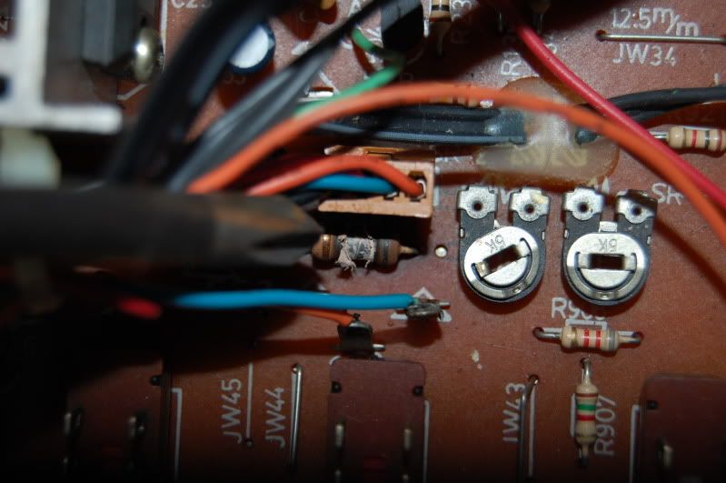
 . I also contacted vienna sound for the resistor color code. He has been working on his wheely and has the same resistor in his, hopefully.....
 ")


 - hopefully it will come back in full working order.