Check your DMM. Many have a Hz feature which may be combined with the AC setting. If you don't have it, you'll either need to get a DMM with that feature or better yet, get a dedicated frequency counter if you really want to continue working on boomboxes. That capability is invaluable because every stereo boombox requires you to measure the pilot signal to set the stereo accurately. The thing with playing with the VR and midpoint thing is that it's just a ballpark way of adjusting it. Also, for accurate setting of tape speed, nothing beats a frequency counter and a calibrated tape for perfect playback speed. For example, a calibrated tape at 3000 rpm set to 3000 rpm.... not 2935, not 3098 but 3000. Or 3003, etc.
National/Panasonic RX-5350 problems.
- Thread starter Tinman
- Start date
I tried grounding pin 9 and nothing happened in either stereo or mono modes.Check your DMM. Many have a Hz feature which may be combined with the AC setting. If you don't have it, you'll either need to get a DMM with that feature or better yet, get a dedicated frequency counter if you really want to continue working on boomboxes. That capability is invaluable because every stereo boombox requires you to measure the pilot signal to set the stereo accurately. The thing with playing with the VR and midpoint thing is that it's just a ballpark way of adjusting it. Also, for accurate setting of tape speed, nothing beats a frequency counter and a calibrated tape for perfect playback speed. For example, a calibrated tape at 3000 rpm set to 3000 rpm.... not 2935, not 3098 but 3000. Or 3003, etc.
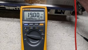
I checked my Fluke and sure enough that had the AC Hz function.
I put it on pin 12 and it was around 20.4.
I can't adjust it while holding the lead on the pin since it's too congested in there so I had to turn then check it but I got it dead on 19khz.
Unfortunately it still didn't lock into stereo and the lamp pin was still showing 7.8v.
I guess I should try another mpx chip.
Three month update on this.
Today I tried yet another mpx ic, a Matsushita an362.
This is the third brand I've tried.
The original was a Rhom 1320, which I'm still not sure if it was correct or not.
I've tried two other Rhom 1320s and an NTE 1248.
They all had basically the same voltages on all pins.
The Matsushita was giving slightly higher voltages all around so I went back to a Rhom.
Looking for something different to try, I actually got the FM stereo and ambience modes to work but it was completely jury rigged.
In mono, I found 7.61 volts on wire #1 of plug cp1 (connects the tuner board to the main board).
When switched to stereo or ambience it dropped to .221 volts.
When grounding pin 9 (IF muting) on the mpx ic, it turns the FM stereo led on but does nothing else as far as I can tell.
I fed 7 volts from my DC power supply into wire #1 of cp1, then switched it to stereo and ambience modes, the radio stayed on but they aren't actually in stereo or ambience, I assume they're still mono.
Once I grounded pin 9, mono, stereo and ambience modes work like they should.
The only problem is that the FM led stays on in mono.
I can probably jury rig this permanently (without using my DC power supply of course) but I'd like to get it working correctly if possible.
Any idea why this works and/or what might be the underlying problem with this?
Maybe this is a clue for what you should be looking at next. Presumably these are the conditions that the MPX chip is looking for to generate a stereo output. Is there a switching issue preventing pin 9 from getting ground or +7v to wire #1 of CP1?
Also I'm presuming when you say FM led, you are saying stereo led?
Also I'm presuming when you say FM led, you are saying stereo led?
I was thinking, with the main power off, I could try unplugging cp1 and feeding 7v into #1 and trace where it goes into the main board.
I could also try taking wire #1 out of cp1, plugging cp1 back into the tuning board and powering everything up normally then try feeding 7v into wire #1 and see if the stereo comes on.
I'm assuming the problem is in the main board but this would verify it.
Pin 9 does change in voltage when switched from mono to stereo but it doesn't seem to be fully grounding out because the stereo led doesn't turn on unless I ground 9 manually.
Yes, it's the FM stereo led.
It'd be great if someone with a National/Panasonic version could verify which mpx ic they have.
(Btw, the name is Rohm not Rhom like I wrote above)
Ok, I tried a few things.
The one thing that worked was taking wire #1 out of cp1 and feeding 7.6v into the tuning board.
The 7.6v on wire #1 gets turned off when switched to stereo or ambience.
Feeding a constant 7.6v into the tuning board has mono, stereo, ambience and the stereo led working correctly.
When I get time, I'll probably just run a jumper from the mono/stereo switch, where the 7.6v originates, directly to the #1 wire into cp1.
It's not perfect but everything will work correctly, which is what I want.
I wish I could find a replacement tuning capacitor.
This one works but is a little temperamental.

When I look at the schematic for panasonic RX-5350, pin 9 of the demodulator is connected directly to ground and not switched. Datasheet for BA362 shows the same thing. Did you verify that this pin on your pcb is getting a good ground? Also, CP1 pin 1 of panasonic version is indeed switched and cut off when stereo or ambience so it appears that is correct, but of course your version is different than the regular version.
This is a different mpx ic than the Panasonic.
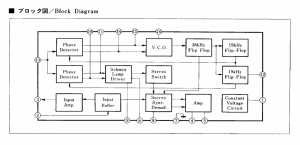
That uses a ba1355, mine is a ba1320.
On mine, pin 7 is the ground.
You can check out the ba1320 diagram below.
I did see that the wire 1 is switched off in st/amb on the Panasonic.
I don't know why this is working like it should when feeding the 7.6v into it.
It seems like pin 9 drops it's voltage lower in st/amb mode with the 7.6v present on wire #1 which I assume triggers the muting and FM led to turn on.
I swear I checked every resistor and diode on this board.
I even took several transistors out that are in the mpx path and tested them.
I'm totally baffled by this thing.
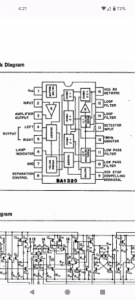
If you read my post more clearly, I was mentioning BA362, which is what you indicated you installed on post #44. Here is the block diagram for BA362, which I believe is the same or similar enough to the other chips you've mentioned.
Yes, pin 7 is the IC ground. Pin 6 is from the stereo led, which is powered by a separate source. Pin #6 goes into the lamp driver of the IC and exits to pin#9, which needs ground in order to light the led. Without a ground at pin#9, the led will not light. I suspect that the presence of ground at pin #9 also triggers the internal stereo switch.
********************
Here is a test circuit for this chip:
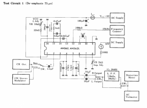
Again, notice how the stereo lamp gets constant positive source voltage separate from the IC. It enters pin#6, notice how pin#9 is connected to ground.
*************************
Here is the application circuit:
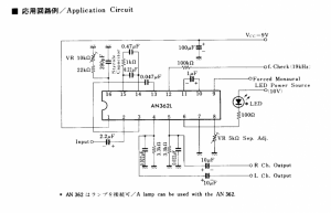
You'll notice how both circuits are very similar. From my experience, designers that use IC's typically adhere quite closely to the manufacturers datasheets and recommended application circuits. Although your 5350 is lacking the schematic diagram, you can be pretty sure that the actual schematic for this portion of the circuit is going to be very close. Notice once again, that the LED enters pin#6. If you follow the block diagram, you'll see that lamp driver is connected to pin#9 which needs ground to complete the led circuit, without which the led circuit is not going to activate. Also note how that same lamp driver is connected to the internal IC stereo switch which according to the block diagram, is tied to the stereo demodulator (also pin 2 goes there too, and pin#2 is the AF input). On this application circuit, you'll notice that pin#9 says "forced monaural". In other words, that pin can be used to force the chip to go into mono mode. How does it do this? I suspect that when the pin gets ground, it completes the circuit for the LED and also triggers the internal stereo switch to activate. To force mono, just remove ground.
So, once can conclude that proper operation requires pin#9 to be grounded for stereo operation, and "without ground" in forced mono. Whether this involves driving pin#9 high, or just untether from ground, I can't say.
Once thing that you didn't really clarify.... you keep referring to pin#1 of CP1. I don't want to refer to the Panasonic schematic since your circuit is apparently different. Where exactly does the pin#1 circuit go to with respects to the MPX chip? Did you trace it?
Yes, pin 7 is the IC ground. Pin 6 is from the stereo led, which is powered by a separate source. Pin #6 goes into the lamp driver of the IC and exits to pin#9, which needs ground in order to light the led. Without a ground at pin#9, the led will not light. I suspect that the presence of ground at pin #9 also triggers the internal stereo switch.
********************
Here is a test circuit for this chip:
Again, notice how the stereo lamp gets constant positive source voltage separate from the IC. It enters pin#6, notice how pin#9 is connected to ground.
*************************
Here is the application circuit:
You'll notice how both circuits are very similar. From my experience, designers that use IC's typically adhere quite closely to the manufacturers datasheets and recommended application circuits. Although your 5350 is lacking the schematic diagram, you can be pretty sure that the actual schematic for this portion of the circuit is going to be very close. Notice once again, that the LED enters pin#6. If you follow the block diagram, you'll see that lamp driver is connected to pin#9 which needs ground to complete the led circuit, without which the led circuit is not going to activate. Also note how that same lamp driver is connected to the internal IC stereo switch which according to the block diagram, is tied to the stereo demodulator (also pin 2 goes there too, and pin#2 is the AF input). On this application circuit, you'll notice that pin#9 says "forced monaural". In other words, that pin can be used to force the chip to go into mono mode. How does it do this? I suspect that when the pin gets ground, it completes the circuit for the LED and also triggers the internal stereo switch to activate. To force mono, just remove ground.
So, once can conclude that proper operation requires pin#9 to be grounded for stereo operation, and "without ground" in forced mono. Whether this involves driving pin#9 high, or just untether from ground, I can't say.
Once thing that you didn't really clarify.... you keep referring to pin#1 of CP1. I don't want to refer to the Panasonic schematic since your circuit is apparently different. Where exactly does the pin#1 circuit go to with respects to the MPX chip? Did you trace it?
Wire 1 traces back to pin 9 with a few resistors and a cap or two along the way.
It looks like pin 12 on the Panasonic would be equivalent to my pin 9.
The Panasonic schematic is showing a diode but I don't believe mine has one.
The first resistor knocks the voltage down from the 7.6v to about 2.2v which is what is on pin 9 when in mono.
I believe when wire 1 is connected to the tuning board and I feed the 7.6v (from my DC power supply) into cp1, I have to ground pin 9 to get st/amb to work.
If I lift wire 1 out of cp1 and apply a constant 7.6v directly to the tuning board, everything works correctly without me having to ground pin 9.
It appears that having the constant 7.6v fed into the tuning board helps pin 9 go to ground when switched to st/amb.
Again, I'm not sure why but it works 100% correctly.
I believe the tuning boards are the same between all three brands.
Looking at that schematic, I see four pins on ic2 that have 7.4v when in FM mode (I'm assuming that would be my 7.6v).
Possibly one or more of those need the 7.4/7.6v to help ground pin 9?
That Matsushita AN362 that I tried was giving voltages that were about 1v higher on most of the pins compared to the three Rohm 1320 and the NTE1248 so I decided not to use that.
Also, it wasn't changing voltages at pins 9, 12 and 16 the same as the four other ones so even though it shows to be an equivalent chip (equivalent to the Rohm 1320 and the NTE1248), it didn't seem to act the same as they do so I'm going to stick with the Rohm since that was in it originally.
I still haven't had time to get this wired to try it out but hopefully I'll find time in the next couple of days.
I appreciate you following up with this Super.
Unfortunately I had to use a buck converter to get the 7.6v.
I got everything run yesterday and now FM mono, stereo and ambience work like they should but I lost AM and the short waves, which I'm fine with.
I got everything run yesterday and now FM mono, stereo and ambience work like they should but I lost AM and the short waves, which I'm fine with.
A lot of work (and time) has gone into this, probably more than any other box I've worked on.
I've got most of it working except the AM and two short waves which, again, I'm fine with.
The work I've done to get the FM stereo and ambience modes working can be reversed by someone in the future if they think they can figure out what the problem actually is.
I decided to add bluetooth to it and am happy I did, it sounds excellent.
This is the first box out of at least 30 I've refurbished over the last four years that's not 100% working.
I got this monster reassembled yesterday and am happy with the overall results.
Thanks for everyone's input on this, especially Sd's.
![PXL_20230704_193246240[1].jpg](/forum/data/attachments/41/41270-a262a81a4c5817c4a77fe029ebb0950c.jpg)
I've got most of it working except the AM and two short waves which, again, I'm fine with.
The work I've done to get the FM stereo and ambience modes working can be reversed by someone in the future if they think they can figure out what the problem actually is.
I decided to add bluetooth to it and am happy I did, it sounds excellent.
This is the first box out of at least 30 I've refurbished over the last four years that's not 100% working.
I got this monster reassembled yesterday and am happy with the overall results.
Thanks for everyone's input on this, especially Sd's.