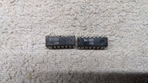
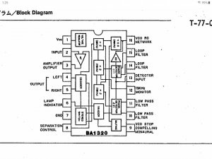
National/Panasonic RX-5350 problems.

Tinman

Member (SA)
Mar 4, 2019
518
264
63
USA
Why do you say that your National is not a Japanese model? Is the FM tuner range 76-108? Regardless, this model has lots of issues with the PCB's degrading over time. There are a lot of printed traces that included resistors printed directly onto the PCB. They probably did this in carbon layers built up until they arrived at the desired resistance value. These tend to degrade over time. Modern double sided boards do not have this problem because they employ all copper traces on both sides, but this is an early attempt, and these were not expected to survive 45 years later. Essentially any or ALL of the traces on the component side can deteriorate. You will need to check them one by one, and YES it is a tedious task, and NO, there is no easy way around it. You can fix this with basically a DMM, without a scope but it is time consuming. I would suggest you focus on the area around the MPX IC since that is where your issues appear to be but an issue can manifest everywhere. The service manual does have voltage specs for the semiconductors. Do a Voltage, Resistance check throughout the area and chart it. Make sure settings prescribed is in the correct position as voltage will change depending upon the mode and settings. Then compare to the specs in the service manual. Additionally, where there are printed traces connecting between 2 points, this will not be obvious in the schematic which will just show a line like normal. The best thing to do is to test for resistance between those 2 points directly at the solder pad. If there is a 220R resistor in between 2 points, it should read 220 from those 2 solder pads. If there is no resistor, it should read near 0. If there readings are off, you will need to jump those 2 solder pads with a wire, or a resistor if the resistance has drifted far from specs (after cutting the printed connection to sever it and prevent parallel resistance). All of this is described in the 2 threads below, I will not rehash scores of hours of work and typing. BTW, you will also have to check the switches S3 and S5, make sure to test for proper operation with DMM directly at the pins.


Yes, my tuner is the full 76-108 FM.
According to a member from an old thread here:

"1. National for Asia
2. Panasonic for US and Canada
3. NP for Europe and Middle East
Not sure about South America probably NP"

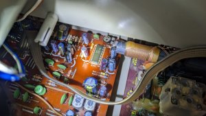
I've gone over the printed side numerous times with a magnifying glass looking for cracks, breaks or cuts and couldn't find anything wrong.

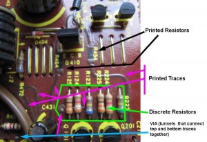
I'm confused about printed circuits and resistors on the main board.
On the tuner board, they're easy to see on the top/component side.
I'd gladly take the time to trace and check printed circuits and resistors.
I see they show many of them on the main circuit board picture (exactly like the tuner board picture) in the Panasonic service manual but I don't see them on this main board.
I've shown a light through the board and still don't see any.
I'll take another look tomorrow but don't know how I could be missing them.
Thanks.
 

Superduper

Member (SA)
printed_trace_resistors.jpg

You really need to read both of those threads I linked to. In those threads, I went through step by step how I fixed the BluFuz RX-5350 which had dead FM, AM, SW, and no MPX (stereo). The photo above shows the topside printed traces and printed resistors. Notice R454 and R464. If you’re looking for a normal barrel resistor, you’ll never find it. Also those printed traces you see is on the top side and while they may be on the schematic, you’ll never find them on the bottom side. Nobody outside of Japan reads Japanese. So if you see a service manual in Japanese, that means that product was intended for the Japanese market.
 

Tinman

Member (SA)
Mar 4, 2019
518
264
63
USA
View attachment 56672

You really need to read both of those threads I linked to. In those threads, I went through step by step how I fixed the BluFuz RX-5350 which had dead FM, AM, SW, and no MPX (stereo). The photo above shows the topside printed traces and printed resistors. Notice R454 and R464. If you’re looking for a normal barrel resistor, you’ll never find it. Also those printed traces you see is on the top side and while they may be on the schematic, you’ll never find them on the bottom side. Nobody outside of Japan reads Japanese. So if you see a service manual in Japanese, that means that product was intended for the Japanese market.
Ok, they're easy to see like on the tuner board, I thought maybe they were a different type and hard to spot.
My main board doesn't have any printed traces or resistors on it.
It's amazing these versions are that different but there's none on mine.

I just did a search again for National/Panasonic RX-5350 service manual, I was mistaken.
The results are for the National only brand not the Nat/Pan.
 
Last edited:

Tinman

Member (SA)
Mar 4, 2019
518
264
63
USA
Ok, now I'm more perplexed.
I've been testing more carbon resistors and found one with 0 ohms across it.
It has brown, black, blue and gold rings.
It appears to be a 10m ohm resistor.
I removed and tested it and it won't settle on a value, instead it keeps fluctuating between 1m and 3m.
If I move the test leads, the value fluctuates even more.
Even if there's a problem with the resistor, when I test the solder pads I removed it from, it's showing 0 ohms across them.
So now I'm thinking something is shorted.
Here's a pic of it in circuit when I thought it was the problem.
PXL_20230228_181202349.jpg
 

blu_fuz

Moderator
Staff member
Jun 3, 2009
10,669
168
63
40
WI
Looking at your picture of the board, its seems you are correct that you don't have any printed traces like my Panasonic does.

Here is a picture of my board around the same place as your picture.

post-83-0-17712100-1390169525r.jpg
 
  • Like
Reactions: Tinman

blu_fuz

Moderator
Staff member
Jun 3, 2009
10,669
168
63
40
WI
Same here showing my printed traces and VIA holes, which your picture does not appear to have:

post-83-0-27300400-1390171690r.jpg
 

Superduper

Member (SA)
Ok, now I'm more perplexed.
I've been testing more carbon resistors and found one with 0 ohms across it.
It has brown, black, blue and gold rings.
It appears to be a 10m ohm resistor.
I removed and tested it and it won't settle on a value, instead it keeps fluctuating between 1m and 3m.
If I move the test leads, the value fluctuates even more.
Even if there's a problem with the resistor, when I test the solder pads I removed it from, it's showing 0 ohms across them.
So now I'm thinking something is shorted.
Here's a pic of it in circuit when I thought it was the problem.
10m Ω is a lot. I've found that most surfaces, even clean looking ones have an oxidation layer that could interfere with reliable readings. If you clean and polish the probe tips with metal polish or steel wool, and perhaps the resistor leads, I bet the readings will settle down. Regardless, if you have an electronics store nearby, resistors are cheap. I would just go ahead and replace any with suspect values.

As for the short.... IF that is a bleed resistor, it's function could just be to bleed off stored current. There is a switch nearby. I wonder if you flip the switch, would that circuit open up. If yes, the "short" might not really be a short but rather a properly functioning circuit. Without a circuit diagram, it's anyone's guess.
 

Tinman

Member (SA)
Mar 4, 2019
518
264
63
USA
10m Ω is a lot. I've found that most surfaces, even clean looking ones have an oxidation layer that could interfere with reliable readings. If you clean and polish the probe tips with metal polish or steel wool, and perhaps the resistor leads, I bet the readings will settle down. Regardless, if you have an electronics store nearby, resistors are cheap. I would just go ahead and replace any with suspect values.

As for the short.... IF that is a bleed resistor, it's function could just be to bleed off stored current. There is a switch nearby. I wonder if you flip the switch, would that circuit open up. If yes, the "short" might not really be a short but rather a properly functioning circuit. Without a circuit diagram, it's anyone's guess.
You're right because after posting it, I switched the rec mode switch which is close by and it had a pretty high resistance between the two pads.
So that's not my problem either but I might buy a 10m ohm resistor just to make sure it's working correctly.
Of course no Radio Shacks or anything else around me anymore so it'll be an online order.
After getting it back together, I tried both the rec mode switch and the manual knob and both registered on the meters through the mics so I'm pretty confident they're working ok.
I also just replaced the TPS switch while I had the soldering iron out.
Of course initially I installed it backwards but it's in and working like it should.

This is frustrating being so close to have it fully working.

To update, the things not working are stereo and ambience modes along with the music meters and the FM stereo led in those two modes.
However the tuning meter works in both modes.
Mono works perfectly.

Thanks.
 

Tinman

Member (SA)
Mar 4, 2019
518
264
63
USA
I just tested the new TPS buton and it works.
Thanks SD for verifying it should lock on.
It's a small thing but keeps me wanting to move ahead and get this finished.
Btw, today I tested all resistors on the main board and the one I referred to above was the only one that gave me an odd reading.
I'd replace the ambience chip but can't find one anywhere.
 
  • Like
Reactions: blu_fuz

Tinman

Member (SA)
Mar 4, 2019
518
264
63
USA
Today I checked the diodes which all looked good.
I also removed the mono/st/amb switch again and took it apart.
Everything looks perfect and it checked out with my dmm.
You know you're getting desperate when you start going over things that are known to be good.
Continuing in the desperation vain, I'm wondering if someone switched the mpx chip out at some point and used the wrong one.
Mine has a ba1320 instead of ba1355 which is shown in the Panasonic manual.
Of course these models are proving to be fairly different so the ba1320 could definitely be correct.
The original mpx that I replaced is on the left and one of the new ones I bought is on the right.
I'm curious if Panasonic used a generic or name brand chip.
PXL_20230301_191020461.jpg
Here's a shot of where it is on the board in case someone has theirs apart and wants to check.
PXL_20230301_193302723.jpg
 

Superduper

Member (SA)
I would not be surprised if your "new" chip is a counterfeit. That is a big problem these days. The only option is to buy from known well reputation sellers. Ebay does not count.

I also was thinking about the possibility that the chip was swapped, but then concluded that it couldn't be that simple. Could it? On the other hand, they are both 16 pin jobs so one wonders.... You can probably check pretty easily by analyzing your circuit vs the datasheets of both MPX chips. The BA1320 datasheet is still available online. I can't find the BA1355 datasheet but if you look at the service manual, it does provide a basic IC diagram. A cursory inspection quickly shows that they are not pin compatible. In the most basic sense, the ground and VCC pins are not the same and you can check on your pcb pretty easily. Also, the BA1320 datasheet shows a sample circuit. In my experience, most manufacturers that put components into service typically mirrors the recommended sample circuit quite closely, so you can check the datasheet against your PCB wiring and you should be able to identify if it's consistent.
 
  • Like
Reactions: Tinman

Tinman

Member (SA)
Mar 4, 2019
518
264
63
USA
I would not be surprised if your "new" chip is a counterfeit. That is a big problem these days. The only option is to buy from known well reputation sellers. Ebay does not count.

I also was thinking about the possibility that the chip was swapped, but then concluded that it couldn't be that simple. Could it? On the other hand, they are both 16 pin jobs so one wonders.... You can probably check pretty easily by analyzing your circuit vs the datasheets of both MPX chips. The BA1320 datasheet is still available online. I can't find the BA1355 datasheet but if you look at the service manual, it does provide a basic IC diagram. A cursory inspection quickly shows that they are not pin compatible. In the most basic sense, the ground and VCC pins are not the same and you can check on your pcb pretty easily. Also, the BA1320 datasheet shows a sample circuit. In my experience, most manufacturers that put components into service typically mirrors the recommended sample circuit quite closely, so you can check the datasheet against your PCB wiring and you should be able to identify if it's consistent.
I'll check the grounds which are pin #7 on my ba1320 and #9 on the ba1355.
Such an easy way to confirm it and I'm not sure if I would've thought of it on my own.
Thanks.
 

Tinman

Member (SA)
Mar 4, 2019
518
264
63
USA
Pin 7 is ground so the ba1320 is the correct ic.
I'm frustrated at this point so I think I'm going to put this away for a while.
I'd never buy another box unless I knew beforehand that I have a service manual for that exact brand and model even if it's described as fully working.
Unfortunately the next (and possibly last) box I'm going to refurbish is a Sears SR2199 which doesn't have a manual available.
As of right now it's a fully working unit so hopefully it works out.
Thanks for the input on this 5350.
 

elezaregilsja

New Member
Oct 31, 2019
12
2
3
Ok, they're easy to see like on the tuner board, I thought maybe they were a different type and hard to spot.
My main board doesn't have any printed traces or resistors on it.
It's amazing these versions are that different but there's none on mine.
maybe because the models 5350 and 5350f are different
 

Josh9994

Member (SA)
Jan 6, 2019
21
12
3
42
AZ, USA
Pin 7 is ground so the ba1320 is the correct ic.
I'm frustrated at this point so I think I'm going to put this away for a while.
I'd never buy another box unless I knew beforehand that I have a service manual for that exact brand and model even if it's described as fully working.
Unfortunately the next (and possibly last) box I'm going to refurbish is a Sears SR2199 which doesn't have a manual available.
As of right now it's a fully working unit so hopefully it works out.
Thanks for the input on this 5350.
Have you tried adjusting vr 404, adjustment of 19 kHz pilot signal? I've had those trimmers drift values a bit. That could be your problem.
 

Tinman

Member (SA)
Mar 4, 2019
518
264
63
USA
Have you tried adjusting vr 404, adjustment of 19 kHz pilot signal? I've had those trimmers drift values a bit. That could be your problem.
Funny, I just came back to the 5350 today.
I finished my Sears SR2199 box a couple of days ago.
Unbelievably, the stereo mode wasn't working on that.
In over thirty refurbs, I've never had a problem with stereo mode until these last two.
The radio played in stereo mode but it was actually in mono and the stereo LED wasn't lit.
Wide mode also worked but the stereo LED wasn't on for that either.
I read a ton of stuff and did come across the 19khz pilot signal which turned out to be the problem.
I adjusted the vr and stereo started working along with the LED so that box is working correctly now.

Back to my 5350, the first thing I did today was cleaned and adjusted vr404, unfortunately it didn't work.
I also verified that the stereo LED was good because I read that on some radios if it's not, that could keep stereo from turning on.
I'm pretty much at the end of the line as far as what to try and check on this.
Everything else is working except for stereo and ambience in FM.
If I had a schematic for it, I'd have an idea of what else to check for but there doesn't seem to be any available.
Thanks for the suggestion.
 

Tinman

Member (SA)
Mar 4, 2019
518
264
63
USA
Today I took voltage readings on my ba1320 mpx chip in both mono and stereo modes.
I have no idea if they're correct or not but comparing them to the ba1355 in the Panasonic manual, they're quite a bit different.

Pin# Mono. Stereo
1. 8v 8v
2. 2.9v 2.9v
3. 2.4v 2.4v
4. 2.7v 2.7v
5. 2.6v 2.6v
6. 7.8v 7.8v
7. Ground
8. 533mv 533mv
9. 2v 378mv
10 2.1v 2.1v
11 2.1v 2.1v
12 2.7v 1.4v
13 2.1v 2.1v
14 2.1v 2.1v
15 2.1v 2.1v
16 4.8v 2.9v

Only pins 9, 12 and 16 changed.
Any thoughts?

Screenshot_20230313-132501_OneDrive.jpg
 

Superduper

Member (SA)
Here's what I would do. Check for 19khz signal at test point connected to pin 12. If you are unable to lock 19khz, the IC will not trigger stereo. Also, LED should always be connected to power. It sources it's ground through the MPX IC. We already know the IC is not providing ground because the voltage at pin 6 is not changing. So the question is whether the IC is getting 19khz lock. Check to make sure that the VR connected to pin 12 is actually working. In other words, using DMM, check and verify that the VR is actually making adjustments. If you can verify that VR is not bad, and you have confirmed good FM mono reception, try grounding pin #9 to see if it triggers stereo. If no, then change BA1320. MPX chips do fail pretty regularly.
 
  • Like
Reactions: Josh9994

Tinman

Member (SA)
Mar 4, 2019
518
264
63
USA
Here's what I would do. Check for 19khz signal at test point connected to pin 12. If you are unable to lock 19khz, the IC will not trigger stereo. Also, LED should always be connected to power. It sources it's ground through the MPX IC. We already know the IC is not providing ground because the voltage at pin 6 is not changing. So the question is whether the IC is getting 19khz lock. Check to make sure that the VR connected to pin 12 is actually working. In other words, using DMM, check and verify that the VR is actually making adjustments. If you can verify that VR is not bad, and you have confirmed good FM mono reception, try grounding pin #9 to see if it triggers stereo. If no, then change BA1320. MPX chips do fail pretty regularly.
I did adjust the VR as stated above with no change as far as locking into stereo.
I also removed the VR and cleaned it with CRC electronics cleaner and verified it does change resistance when adjusted so I'm assuming it's okay.
As far as the 19khz signal, I'm not sure how to test for it.
All I have are dmms, no real test equipment.
FM mono has excellent reception even in my basement with the antenna folded and down.
Tomorrow I'll try grounding pin 9 and report back what happens.
Thanks.