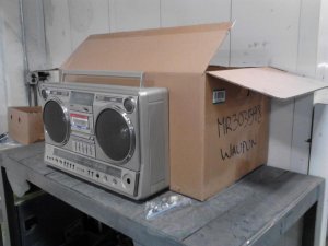
Some of you might have been following this thread so I thought I would update it to let you all know the current status. Recap: Joe has this RX-5350 with a hum/oscillation that could not be resolved. He got to the point where he felt he was stuck and needed more help to get this fixed once and for sall, so we worked something out where he would mail it to me and I would work on it as time permitted.
Some of you might be aware that my life has been really unsettled the past couple years. It still is, hence the reduced number of posts and lack of projects to share. In any event, when the boombox arrived, I did a quick test to verify everything according to my understanding. I immediately noticed that the noise could be changed and intensity varied by operating the mixing control knob. This was never reported or noticed by Joe.
***********
Lesson #1. Thoroughly check and test everything, even if seemingly unrelated. It took me about 2-3 minutes of checking to discover this, long before 1 screw was ever removed. The finding is important as you are about to see.
***********
The boombox then went into my closet for safekeeping since I was not ready to work on it. However, it was clear to me that I would focus on the mixing circuitry since it could certainly be related. Here the boombox sat until recently when Joe began dropping hints about the 5350. Stuff like "I miss my 5350, wink wink", etc.
Anyhow, a couple days ago, I pulled this out, disassembled it and looked it over. I then referred to the circuit diagram to look at the mixing circuit (for those following along, you can refer to the circuit diagram portion to follow).
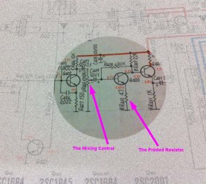
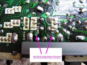
I then tested the appurtenant transistors in circuit and testing showed they tested fine powered down. I then began testing the components. Found one resistor (R410 47R) which could not be seen since it was apparently a "printed" resistor. However, I do know, by looking at the circuit diagram, that the emitter (E) of Q403 is tethered to ground through R410. Therefore, testing resistance between (E)Q403 to Ground should read 47ohms or less. The reason resistor resistance tested in circuit must be the same or less than the value of the resistor itself is that you are reading either the resistor value itself, or the resistor value + any parallel circuitry resistance. Students of electronics will understand how parallel resistance will affect a circuit and if you wish to know, then just google since I don't want to complicate this thread any more than necessary. I read 168 ohms. Something is amiss.
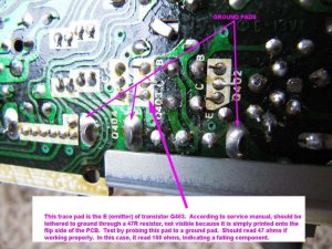
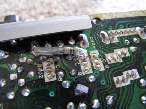
The printed resistor is on the component side of the board and the circuit crosses over through these 2 vias (tunnels that connect traces on different sides or layers of a PC board together).
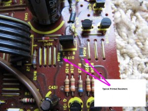
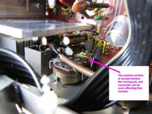
As you can see, no resistor is visible, but there is corossion where the resistor should be. That resistor is located immediately behind the mixing control pot.
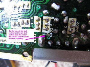
So we are going to fix this by cutting that portion of the bad circuit to isolate it. It might be tempting to just drill through the vias and install a discrete resistor through those holes. Don't. Also, it is possible to calculate an appropriately value resistor to make that circuit 47 ohms total with the failing resistor in parallel with the new one. Once again, don't. That resistor is failing and probably will continue to change in value. Also, there could be stray capacitance introduced that could affect the circuit and maybe cause or allow oscillation to continue. The solution was to simply cut that trace with an exacto knife, make the cut wide enough to ensure no electrical connectivity. See cut.
Now after testing with meter to ensure ohms is infinity between (E)Q403 to ground, we are going to bridge those two with a new 47R 1/4W resistor, embedded in a clear heat shrink tubing. Clear is optional but rather than having future serviceman think it's just a jumper, a clear tubing allows them to see the resistor and value so there's no misunderstanding what was done.
After reassembly, hum was gone and boombox is now quiet. In fact, it sounds dang good, no doubt helped immensely by the recapping job. I am calling this issue, FIXED. For those of you who are just now seeing this thread, and you have A LOT of time, you can go back and read all 13 previous pages. Also note RULE #1 above. Had we observed and noted the relationship of the issue with the mixing circuit to begin with, we probably would have had this fixed long ago without getting it shipped at all.
One last note, while it may seem by following along with this post that this issue was a simple diagnosis and easy fix, I will say and I think Joe will concur that when you see the entire circuit diagram which is 100 times the size of this little snippet, things no longer seem so clear and simple.


")