Well I sure did it this time...

Status
Not open for further replies.

trippy1313

Member (SA)
So, as some of you've read, I'm no longer allowed to buy anymore boomboxes, at least till I get us financed for a new house... So I talked my buddy Mikey into buying this Trc-920 off ebay, he liked what I had already and wanted to get a cool box of his own.... The Function switch and tuner selection don't work... I read a post from someone who fixed there's didn't look to bad, since I'm the more handy one I decided to give it a whirl....

Here's a couple pics... the box was actually pretty easy to take apart, I decided to go with the tuner selection switch first, it's stuck on Phono/Line in, so if I don't fix it, he can still use his iPod.
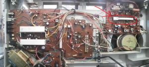
20130815_093713-1.jpg

Cut open the slider gear section, got off the housing, and was looking at the slider in there..... thought, "oh I'll pull it out, make sure it's clean." that was a no-no.... these little guys popped out all over the place!!!! Then... I snapped off the geared part of the slider, circled in red...20130815_170119-1.jpg
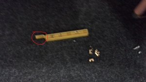
Not happy, had that sick to the stomach feeling.... after messing around with it for a while... plastic welded a section of the tab, till I get some of that solvent weld stuff you all talk about... then tried to put those pieces back in, and slide it back in the slider housing.... they jammed up... pulled it out, a bunch of them were bent... so I spent an hour trying to straighten them, and finally got it back in...

It seems to slide nice, I just have no idea if it''ll work, till I fix the broken gears and put it back together... So like I said.... I sure did it this time....
 

Superduper

Moderator
Staff member
Couple things... first the internals of those switches are much more fragile than people know. Glad you got the feelers straightened and back in but they need to be almost perfect not only in shape but tension as they are/were somewhat spring loaded. You'll know soon enough if you got them in OK by checking operation but there's a possibility that even though assembled, the electrical continuity might never be right again. There's like 5 separate switches inside that all gets thrown at the same time and switches different things.

Secondly, the solvent weld solution does not work on nylon. Many of these switches use nylon actuators. Not sure if that's the case with Lasonic or whether they used plastic.

Worse case scenario is that if the switch has failed beyond repair, you can remove switch and hardwire the boombox it to a particular function with jumpers between the appropriate pads. Don't ask me which goes where -- I don't have/do Lasonics. :lol: Ideal situation would be to hardwire it to the Tuner. Then install a switched mini-jack for the iPod. That allows you to listen to the tuner, but you can listen to ipod-aux-line in by just inserting a ipod plug into the jack which automatically switches out the radio. I have another post where I describe (generally) how it's done.
 

trippy1313

Member (SA)
Superduper said:
there's a possibility that even though assembled, the electrical continuity might never be right again.

Secondly, the solvent weld solution does not work on nylon. Many of these switches use nylon actuators. Not sure if that's the case with Lasonic or whether they used plastic.

I don't have/do Lasonics. :lol:
1. The continuity is my concern with that now, I got them in and it slides nice, but maybe too nice, the feelers I think could be too far apart, and not be touching as well.... we'll see

2. Good to know, maybe I'll just plastic weld the whole think and cover with a thin layer of some glue.

3. Lol, yes I've read a bunch of your posts to know you're not much a fan of Lasonics,

Hopefully I can at least have better luck, and be more aware when I do the Function switch, and be able to get it t switch from phono-tape-radio.
 

floyd

Boomus Fidelis
get in touch with kraftmatic he might have some internal parts for this , i'm not positive but it don't hurt to ask.
 

baddboybill

Boomus Fidelis
Yes even though many Lasonics have different setup of internals. It seems that all of the switches from 920 and 931 are same and interchangeable. So band switches are same and function are same but you can't mix them ;-)


Bad Boy Bill
 

trippy1313

Member (SA)
JVC Floyd said:
get in touch with kraftmatic he might have some internal parts for this , i'm not positive but it don't hurt to ask.

baddboybill said:
Yes even though many Lasonics have different setup of internals. It seems that all of the switches from 920 and 931 are same and interchangeable. So band switches are same and function are same but you can't mix them ;-)


Bad Boy Bill

Cool, that's good to know, If this doesn't work, I'll definitely check with kraftmatic to see if he's got anything I might screw up. Thanks.
 

kraftmatic

Member (SA)
Oh man, good luck with that! When I saw how crazy those switches were I couldn't believe it. I was always wondering why everybody said they were so hard to fix, now I know.

That 920 is just ridiculously complicated for such a small box, it doesn't make sense.

I'm pretty sure I tossed the amp board after I harvested what I could from it, so I don't think I have anything that will help you out besides the knob we talked about. I'll check my parts bin just in case.
 

Superduper

Moderator
Staff member
I actually stored up enough components to build a solder in retrofit for these crappy controls. I have not, and probably will not, get to actually building any for at least a year or two -- time considerations and all that. Basically, it will be a pin-compatible daughter board that will house a relay array and allow those two failure prone switches to utilize standard reliable rotary switches to drive the relay array board. These would not be your run of the mill relays... they look like IC's and will completely resolve the unreliable switch problems. I would need to design and have custom PCB's manufactured so I can build them easier, as it's far too labor intensive to do point to point wiring on a hobby board. But before I build even 1, I would need to investigate the demand for such a retrofit. These Lasonics are getting scarcer and it seems many, perhaps most, are being retired due to this problem.
 

trippy1313

Member (SA)
That's alright Owen, now that i know what Im dealing with ill know not to do it again. :/.

That sounds like a great idea Norm, even though it'll be a while till you get to it, Im sure that'll be a great help to all if you/someone can rig up something like that!
 

Superduper

Moderator
Staff member
I considered that project a long time ago. Somewhere, someplace, I have the switch pin assignment mapping written down but I may have lost it already. I then searched for and stocked up on the miniature IC relays when I found affordable ones at closeout since they are ridiculously expensive (as much as $5 to $15 each) and whole bunch are needed per switch (I think like 9 of them). The IC relays are needed due to their comparatively low power demands compared to standard relays, but also because they are completely epoxy sealed, there's no chance of contact contamination. They should be good for something like 100,000 actuation -- meaning, lifetime. The intended retrofit solution would be to remove the knob, shaft extension, switch. Then the new switch board would install in the place vacated by the old one, and a short cable would interface with a front panel mounted rotary switch. Gone should be the clunky shaft extension and coupler and gears. Anyhow, that was my plan. Project could still be in the works. I am thinking of making 50 of them. Once they all gone, there will be no more. At least, if I ever build it.
 

Superduper

Moderator
Staff member
Don't know yet Bill. I still need to design the PCB on an electronics CAD design program, have somebody in HK or China (that's where they are all being done) custom etch the batch of PCB's for me, and then I need to find suitable collection of rotary switches that will work for this application at an affordable cost (that's one component that I haven't accumulated yet), and then I need to evaluate the total cost for all of it. It will not be a $10 thing though... I also will need some hardware too since the new pcb needs to be mounted on a pedestal type of pin extenders to interface the new board with the original switch location because it's larger than the original switch. Also, while sometimes, you can find a component or small lot of them for what seems like a cheap price, the truth is that they can't be used as the entire project depends on the exact same component being used in the entire project. If I need 9 relays/board (and I'm not sure, it might be more), and I am doing 50 or 100 boards, then I'll need from 500 to 1000 relays. That type of volume requires I buy from larger electronics suppliers and those components will cost more. The reason is that each component has a particular size, layout, pin-out, etc, and when I design the board, I need to know the specifications beforehand and it needs to be consistent throughout the entire run.

Bottom line... can't commit to pricing until I am able to accumulate all the parts and get a bid for the PCB etching. As you might know, 1 single custom board prototype can cost as much as $100 to etch/cut before populating with components. Price gets lower depending upon size/volume. All of this needs to be investigated. I can tell you however that it's my goal to be able to get a complete kit available for under $50 but not sure that's possible. Too low means not practical and not worthwhile for me to do. Too high and nobody will buy so maybe it's a non-starter.

We all know that these two switches are the weak link in these Lasonics. For the right person, it might be worthwhile to retrofit for the right specimen, especially since it'll totally cure the fragile switch syndrone and eliminate that as a potential issue. No more fear of twisting that switch and feeling/hearing that horrible crumbling sound.
 
Status
Not open for further replies.