TEC 878RR Super Jumbo volume issue – only very loud to super loud!

Status
Not open for further replies.

dubout

Member (SA)
I have found a sweet looking super jumbo boombox from first owner in great condition. The TEC 878RR is known to be an aka of ICS STR-5099A, the Willtech MG-930E, and the Silver RG-6000W according to wikiboombox.

Everything works like a charm with no crackling etc. except the volume is very loud even when the volume slider is set to zero. The slider still works as the box gets louder when the slider is moved. But it doesn't cut out the sound or even reduces the volume level to a bearable level.

Maybe a useful hint: Both tape decks run incredibly fast, even with cleaned pinch rollers.

I already replaced the biggest cap on the amplifier board as I thought this might deliver the wrong voltage from the beginning but no luck.

As I couldn't find any service manuals maybe someone can help me find out where to look?

s-l1600.jpg
 

Superduper

Moderator
Staff member
No manuals are likely to exist for these non mainstream models. If I were to take a guess, I’m gonna say it sounds like your volume control is knackered, probably loose feeler or debris inside that is shorting the contacts. Voltage issue would never have such symptoms. Excessive voltage might result in higher and distorted volume levels at the upper range but a properly functioning pot would always throttle the signal to nothing. An excessively highly voltage supply would more likely result in toasted components or circuits rather than what you’re describing.
 

dubout

Member (SA)
I have desoldered and cleaned the slider twice, it looks like new. Also, if I shine a lamp underneath the black plastic, all feelers seem to touch the carbon track.

All this doesn't say you are wrong, superduper. In fact, I also think there is something wrong with the feelers. Or the connections between the carbon track and the pins. I just hoped it was something else as it looked so good. :(

These sliders with that design are impossible to find, at least for me. I had a non working slider in my Silver SR 5000 and wasn't able to track down a replacement. I ended up buying a donor box.

I will have to put this aside and keep my eyes open for replacement. This slider is marked with SINO on the black plastic and B100K on the board.

20230211_142326.jpg20230209_200543.jpg
 
Last edited:

caution

Member (SA)
Did you try hooking up a meter to the pot and sliding it to see if it gives you reasonable resistance values?
 
  • Like
Reactions: dubout

Superduper

Moderator
Staff member
Ugh... that's a really really cheap volume pot. Ok, let me tell you what I think is going on here.

IMG_7626.jpg

Consider how a (simple) normal pot is supposed to work in an audio situation.
In example #1, the signal enters the mid point of the pot. Some signal will get shunted to ground, and some signal gets sent to the amplifier to be output to speakers. In example #2, the signal enters the bottom of the pot and with little resistance to ground, most if not all of the signal gets sent to ground with non or little going to the amp, result in no volume. Example #3 shows what happens when the volume pot is at max, signal enters the end of the resistor, so most all signal goes to the amp. The signal would have to travel through the entire resistor in order to reach ground so it takes the easier path to the amplifier. Result, max amp signal.

IMG_7625.jpg

In example #4, you will see that in the case where there is a broken connection at the circuitry that connects to ground... what happens is that even with the pot set to minimum, all of the signal will be routed to the amplifier, although the signal will see resistance, that path is still much easier to traverse than the path to ground which in this example is broken. So the signal is slightly attenuated to the amplifier, but it will still result in significant volume at the amplifier. Then consider example #5, with the same broken ground and the volume control set to maximum. Once again, all the signal gets to the amplifier but without the resistance element to block it, so the amplifier gets full volume, even more than if the ground circuit was unbroken, which if integrity was kept, would still result in a slight amount of signal getting shunted to ground. Result: ultra loud. In #4 and #5, the volume control was set to minimum and maximum but in both cases, the volume at the amp will be high, although higher with the setting at maximum since although current will be reduced in the minimum position because the signal has to go through the resistor, voltage will still be high.

In the last example, this is probably reserved for very complex circuits, in which other components are at play for various reasons. This scenario is almost certainly not the case because in a simple boombox like this, they would never need to insert other components that adds costs and complexity. The name of the game on cheap boombox is simple and cheap. But if in this case, the resistor was open or the capacitor shorted, that could have some affect on the signal. For the purposes of this boombox, just ignore that this example is even presented here.

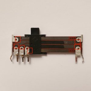
What could be wrong with your control? My educated guess is that the rivets that connects the resistor tracts have broken. You can confirm this with your DMM. Luckily, you can also fix this pretty easily with conductive epoxy. Use only enough and don't spread it too far off track otherwise you could cause shorts or change the resistance curve. A little change probably won't be noticeable. These epoxies aren't cheap but you don't need a lot and they don't have good shelf life so just buy what you need, no more. Also make sure they are properly cured before use. Conductive epoxies aren't conductive or fully conductive until they've cured. Some requires heat curing.... this may involve a short time in the oven. Don't worry, just don't tell your wife, she won't know. It's not like you are trying to bake an automotive cylinder head.
 
  • Like
Reactions: dubout

hopey

Member (SA)
Yes those slide pots are bad but easy to clean. I found a sony mini that was doing the same thing the volume was getting louder and louder then went full scale. I think either the carbon tracks gone haywire or the amp chip itself.
 
  • Like
Reactions: dubout

dubout

Member (SA)
Thank you so much for taking me by the hand and guiding me through the most basic functionality of a potentiometer, superduper! I tried to figure out how they work and to some extent they are self explanatory. But my sorry a** never was able to transfer that to the one(s) in front of me to find out if it was faulty or not. I only can go by trial and error. But the slightest unexpected result puts me off and makes me wonder if it's the component's fault or mine.

I will order cunductive epoxy and then do as all of you suggested: First I will desolder the slider again and find out how it works. Then I will try to fix it. I will let you all know!
 

Superduper

Moderator
Staff member
Your symptoms are completely consistent with a broken ground. Although it's possible the break could be on the PCB circuitry or a ground wire somewhere, I find that far less likely and based on experience and what I can see of the construction of that slider, the most likely break is at the connection between the rivet and the slider resistor board trace. As I already said, it's easy to check with a DMM, whether the riveted is actually electrically connected to the slider trace. You may want to confirm it before plunking down the $$ for the epoxy.
 
  • Like
Reactions: dubout

dubout

Member (SA)
I desoldered the slider an checked it as far as I am able to. When I put the DMM on the traces, I get readings I understand: around 1.000 Ohm when the slider is down, around 98.000-99.000 Ohm when it is turned up. So this says the traces and feelers are working as they should.

As soon as I put the DMM on the rivets, I get readings around 250.000 Ohm. Those readings change when I carefully jerk on the feet and the rivet moves. This is proof of what most of you suggested, right? The rivets are bad.

To be honest, I went with conductive glue instead of cunductive epoxy. It just costs a fraction (10 Euro for the glue to 110 Euros for the epoxy on ebay if I was reading right?!) and gives me the chance to solve my problem at least for a while until I might find a replacement. In the end keeping it cheap reduces the (emotional) damage when I screw up big time lol.
 

Superduper

Moderator
Staff member
If you want it fixed right, I highly suggest you stick with epoxy. Epoxy are also glues but not all glues are epoxy. Your slider is going to have stress imparted on it as the knob is pushed side to side and depressed. If the glue you use is a simple apply and dry for an hour type, will it be structural or will it fracture easily? Epoxy is a structural repair. If glue fails, it may complicate another fix attempt with epoxy because removing the old glue may require scraping it off. I probably wouldn’t want to have to tell you that scraping a carbon strip might not end well.
 
  • Like
Reactions: dubout

dubout

Member (SA)
I really appreciate your advice and I simply know that every word you say is true. Please don't think I am unthankful, you helped me many times. Your standards are high and so should be mine. I just can't afford to throw hundreds of Euros at a 20 Euro box. And maybe the glue is good enough and stands the stress as it said it is flexible. *Fingers crossed*

There is plenty of room for the glue to not touch the carbon strip.

I will keep you posted!

20230216_194105.jpg
 

Superduper

Moderator
Staff member
I don’t think I’d be willing to spend that much either but I had no trouble finding lots of examples for under $15. Therefore I don’t understand why you keep saying hundreds of euros for epoxy. The example below is for nickel. Silver based is even better and costs just a little more.
 

dubout

Member (SA)
It worked! The glue was said to dry within an hour but it took three days to dry and to become conductive. I am so happy! Thanks to all who contributed and special thanks to superduper for giving me basic understanding of how potis work.

I still had the problem of fast running tape decks. Fast meaning a three minute song ran through in 20 seconds. There is a small poti on the board and a hole in the motor. Both had no effect. The measurements were 12 volt as it should. Luckily I have a donor Elite Electronics RR 5660 box (also a beautiful three piece btw.) with the same double tape mech where I already took some plastic pieces from to complete the TEC tape mech. And voila, the new old motor works! There must be a short inside the faulty motor.

Now I have a fully working Super Jumbo in nice cosmetic shape thanks to you guys.
 
Last edited:

hopey

Member (SA)
It worked! The glue was said to dry within an hour but it took three days to dry and to become conductive. I am so happy! Thanks to all who contributed and special thanks to superduper for giving me basic understanding of how potis work.

I still had the problem of fast running tape decks. Fast meaning a three minute song ran through in 20 seconds. There is a small poti on the board and a hole in the motor. Both had no effect. The measurements were 12 volt as it should. Luckily I have a donor Elite Electronics RR 5660 box (also a beautiful three piece btw.) with the same double tape mech where I already took some plastic pieces from to complete the TEC tape mech. And voila, the new old motor works! There must be a short inside the faulty motor.

Now I have a fully working Super Jumbo in nice cosmetic shape thanks to you guys.
Do have photo of where you placed the conductive glue?
 

dubout

Member (SA)
Do have photo of where you placed the conductive glue?
I forgot to take pictures, sorry. I cleaned the slider with lighter fuel, then with alcohol to wash off any oil from the fuel. Then I roughed up the traces a little with a tweezer and a small piece of a metal sponge. Then washed it with alcohol again. Then I put the glue right to the rivets, see picture. I tried to put the gloe only on spaces where the feelers don't go. I also put some tuner spray on it to make them glide again and to preserve the feelers from corrosion.
 

Attachments

  • 20230216_194105.jpg
    20230216_194105.jpg
    100.8 KB · Views: 7
Status
Not open for further replies.