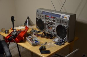
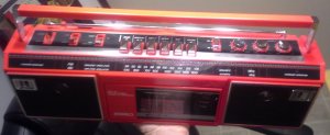
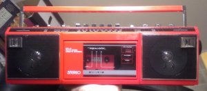
A long-time friend of mine goes by the nickname "Red Box" (in the context of phreaking) so I thought that a little red boombox for Christmas would make a cute gift for her. I snagged a Realistic SCR-30 for $11 from the bay which was pristine on the outside, but advertised as "plays quiet." Uh oh. But, I figured it couldn't be beyond repair if it looked so good on the outside. It's been a while since I really tried to repair a box but I figured this one should be simple.
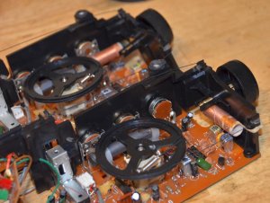
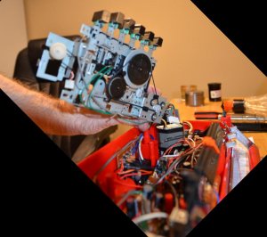
One piece was rattling around inside when I got it, which turned out to be the end of a plastic backplate which acted as a guide for the pushers on the cassette. I gave up trying to glue it, I think it's PTFE. The attach point was so tiny anyway. But, since the piece fit into a larger metal frame for the assembly, and was flanked by another plate for the other side, it stayed put on its own once reassembled. The play button has a little bit of slop in it, but it's fine.
Then I noticed that the pushers activate the motor by coming down on a lateral plate with a diagonal edges in it, so the plate is forced left and right as buttons are pressed down. The guide pins at each end were made of a hard plastic and had long shattered away except for the post of one of them, which I managed to bore out. After using some tiny screws and washers the plate was moving left and right again.
By now all the buttons were functioning again, but not without a lot of slight bending here and there to get things to operate smoothly. It used the same thin metal used in older PC cases, which bends easily. But then I noticed that the tape counter was going up even when I pressed rewind. After analyzing the unique shape of the FF and REW buttons I concluded that a tiny plastic pin coming off a pendulum-looking piece had been sheared off, probably by the diagonal edges of the pushers meant to move it left and right. It looks like if you had tried pressing FF and REW at the same time, or nearly so, it would snap right off from the opposing forces. So, I crudely installed a small screw that sort of fixed it, but cut my losses and it wasn't worth trying to add a pin back into this little plastic piece. Who needs rewind?
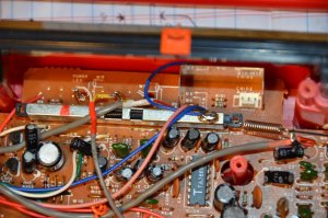
Having gotten all but rewind working, I moved on to the main board, which would allow you to tune in stations, you could see the stereo light going on and off, and at full volume you could hear it, but like it was on the wrong mode setting. Come to find out that the ferrite core snapped in half, with the one half barely stuck in the end of a plastic bracket holding the rest. That bracket fit into the PCB through two RECTANGULAR holes. Some force came down on that spot somehow, and a crack shot out off one of the corners of one of the holes, severing three traces going to the volume knob. After jumpering them the radio came to life!
But, as you turned the volume knob, one channel would cut out. Only wiggling the knob itself remedied the problem, so I figured something was broken inside the slider. So, I desoldered all pins to it (and two huge tabs for a ground shell) and with the luck of the gods was able to flex the board just enough to get it out without having to disassemble the tuning string. Sort of surprised it's still intact with all of my messin' around.
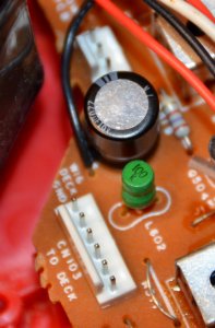
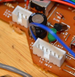
After getting it apart, I noticed that there were six standard pins with a seventh one off the side that wasn't in line with the rest. Except for that seventh pin, It's identical to pic #3 (link). That seventh pin was not making a connection, but the trace was only accessible for maybe 1/32" worth before it went under the tab for the terminal. I scratched away what I could right next to it and added a couple beads of solder to help make a connection better, but after all that horsin' around and getting it back into the board and resoldered, it didn't make a difference. It still cut out. That's when I noticed the pics in the earlier link about the wipers. I tried pressing down a tiny bit on the knob and the channel came right back, so I figured I needed to bend them up. This time though, i figured out that if I only removed the ground shell, I could bend the whole pot back a bit and remove the wiper's case without desoldering the whole thing off the board again.
Having gotten the sliders carefully restored to a higher position, I reinstalled it. I'm not sure where the issue is now, but the lowest position is as loud as the loudest setting used to be, and it only gets louder as you crank it. No re-positioning of the knob within the assembly fixed that. I figure the pot is beyond repair, but it's so custom that the cheapest and most accessible replacement would be another deal on a broken model. It's too bad that there are likely pieces of junk sitting at secondhand stores holding that one part you desperately need, but no way to know which one.
I disassembled and reassembled the cassette mechanism so many times I basically memorized it, haha. Not that I'll ever see another of these exact same mechanisms in a box ever again (Dear God I sure hope not!) but if I do I'll know how to fix it It was interesting learning some of the various techniques used to move things around, as well as some horrible engineering choices.
I'm feeling jazzed and ready to put some work toward a real keeper, and that very special box is crossing this great and frozen land of ours in a USPS long-hauler as I type this, so please keep it in your thoughts and prayers during this tough and trying period.
One piece was rattling around inside when I got it, which turned out to be the end of a plastic backplate which acted as a guide for the pushers on the cassette. I gave up trying to glue it, I think it's PTFE. The attach point was so tiny anyway. But, since the piece fit into a larger metal frame for the assembly, and was flanked by another plate for the other side, it stayed put on its own once reassembled. The play button has a little bit of slop in it, but it's fine.
Then I noticed that the pushers activate the motor by coming down on a lateral plate with a diagonal edges in it, so the plate is forced left and right as buttons are pressed down. The guide pins at each end were made of a hard plastic and had long shattered away except for the post of one of them, which I managed to bore out. After using some tiny screws and washers the plate was moving left and right again.
By now all the buttons were functioning again, but not without a lot of slight bending here and there to get things to operate smoothly. It used the same thin metal used in older PC cases, which bends easily. But then I noticed that the tape counter was going up even when I pressed rewind. After analyzing the unique shape of the FF and REW buttons I concluded that a tiny plastic pin coming off a pendulum-looking piece had been sheared off, probably by the diagonal edges of the pushers meant to move it left and right. It looks like if you had tried pressing FF and REW at the same time, or nearly so, it would snap right off from the opposing forces. So, I crudely installed a small screw that sort of fixed it, but cut my losses and it wasn't worth trying to add a pin back into this little plastic piece. Who needs rewind?

Having gotten all but rewind working, I moved on to the main board, which would allow you to tune in stations, you could see the stereo light going on and off, and at full volume you could hear it, but like it was on the wrong mode setting. Come to find out that the ferrite core snapped in half, with the one half barely stuck in the end of a plastic bracket holding the rest. That bracket fit into the PCB through two RECTANGULAR holes. Some force came down on that spot somehow, and a crack shot out off one of the corners of one of the holes, severing three traces going to the volume knob. After jumpering them the radio came to life!
But, as you turned the volume knob, one channel would cut out. Only wiggling the knob itself remedied the problem, so I figured something was broken inside the slider. So, I desoldered all pins to it (and two huge tabs for a ground shell) and with the luck of the gods was able to flex the board just enough to get it out without having to disassemble the tuning string. Sort of surprised it's still intact with all of my messin' around.
After getting it apart, I noticed that there were six standard pins with a seventh one off the side that wasn't in line with the rest. Except for that seventh pin, It's identical to pic #3 (link). That seventh pin was not making a connection, but the trace was only accessible for maybe 1/32" worth before it went under the tab for the terminal. I scratched away what I could right next to it and added a couple beads of solder to help make a connection better, but after all that horsin' around and getting it back into the board and resoldered, it didn't make a difference. It still cut out. That's when I noticed the pics in the earlier link about the wipers. I tried pressing down a tiny bit on the knob and the channel came right back, so I figured I needed to bend them up. This time though, i figured out that if I only removed the ground shell, I could bend the whole pot back a bit and remove the wiper's case without desoldering the whole thing off the board again.
Having gotten the sliders carefully restored to a higher position, I reinstalled it. I'm not sure where the issue is now, but the lowest position is as loud as the loudest setting used to be, and it only gets louder as you crank it. No re-positioning of the knob within the assembly fixed that. I figure the pot is beyond repair, but it's so custom that the cheapest and most accessible replacement would be another deal on a broken model. It's too bad that there are likely pieces of junk sitting at secondhand stores holding that one part you desperately need, but no way to know which one.
I disassembled and reassembled the cassette mechanism so many times I basically memorized it, haha. Not that I'll ever see another of these exact same mechanisms in a box ever again (Dear God I sure hope not!) but if I do I'll know how to fix it
 It was interesting learning some of the various techniques used to move things around, as well as some horrible engineering choices.
I'm feeling jazzed and ready to put some work toward a real keeper, and that very special box is crossing this great and frozen land of ours in a USPS long-hauler as I type this, so please keep it in your thoughts and prayers during this tough and trying period.


